Passive optical network system and ranging system thereof

a technology of optical network and ranging system, applied in the field of pon (passive optical network) system, can solve the problems of 30 seconds required to activate all the onus at once, and achieve the effect of short tim

Inactive Publication Date: 2008-12-25
HITACHI LTD
View PDF2 Cites 16 Cited by
  • Summary
  • Abstract
  • Description
  • Claims
  • Application Information

AI Technical Summary

Benefits of technology

[0011]The present invention has for an object to provide an OLT, ONU, and PON system making possible the activation of one hundred or more ONUs while making efficient use of the band, and in a short time.
[0012]In order to combine a low band loss and a short activation time, it is acceptable to enable distance measurements of a plurality of ONUs inside one ranging window.
[0014]Also, as another means for attaining the task, the OLT periodically generates, regardless of the presence of an uplink ranging response in the ranging window, plurality of ATC reset pulses, and when the ONU receives a ranging request, it transmits a plurality of ranging responses at an interval which is different from an integer multiple of the aforementioned period. By transmitting a plurality of ranging responses, at least one signal is able to bring the distance measurement to success without colliding with the ATC reset pulse.
[0015]According to the present invention, it is possible to provide an optical access system which, while making effective use of the band, enables the activation of one hundred ONUs or more in a short time, within 1 second.

Problems solved by technology

In this way, the OLT transmits a signal for distance measurement, since there is computed for each ONU an equalization delay time for the same ONU, it is not possible, within the ranging window of one ONU, for other ONUs to transmit an optical signal with respect to the OLT.
However, in this case, there occurs the new problem that 30 seconds are required to activate all the ONUs at once.

Method used


Image

  • Passive optical network system and ranging system thereof
  • Passive optical network system and ranging system thereof
  • Passive optical network system and ranging system thereof

Examples


first embodiment

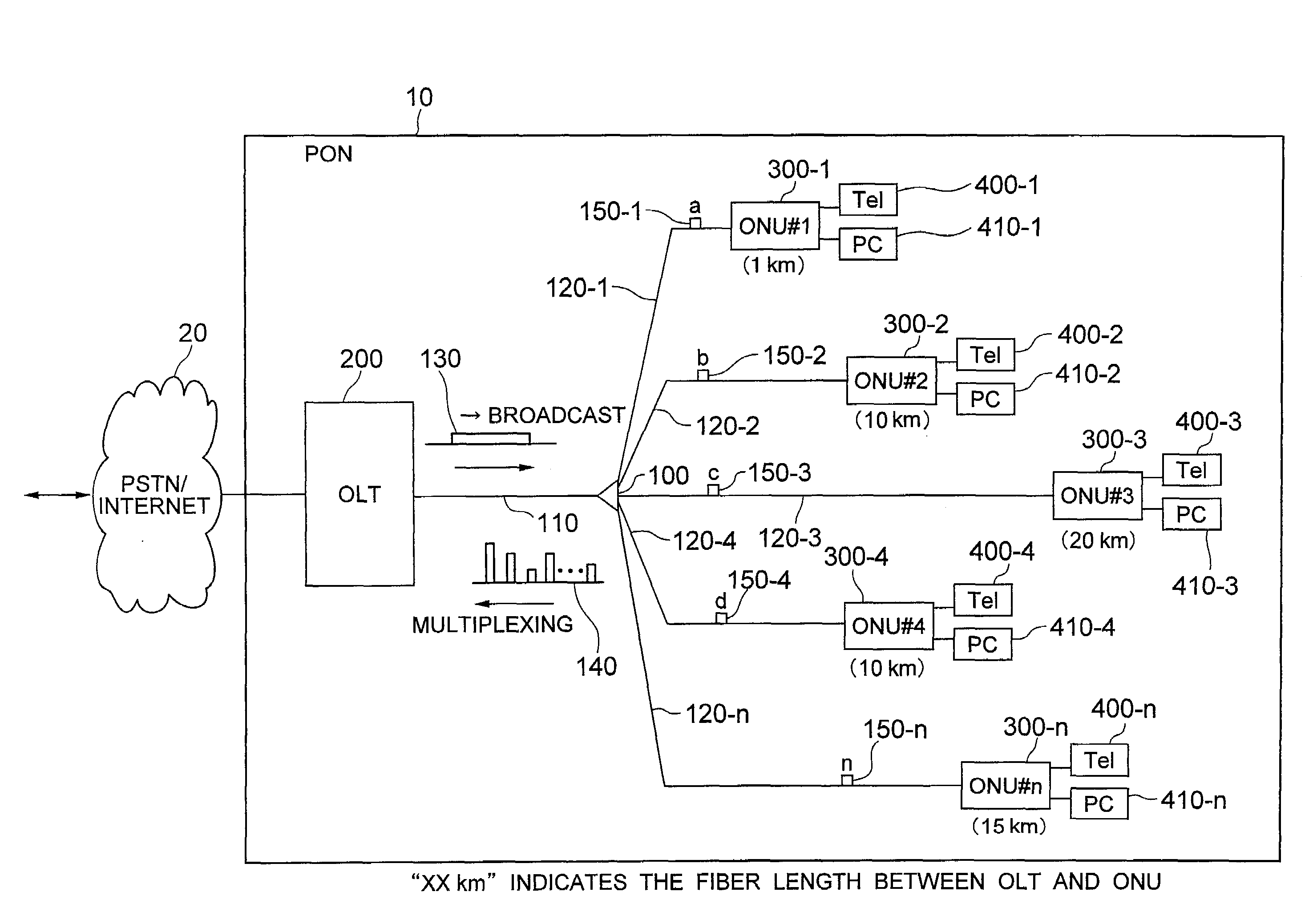
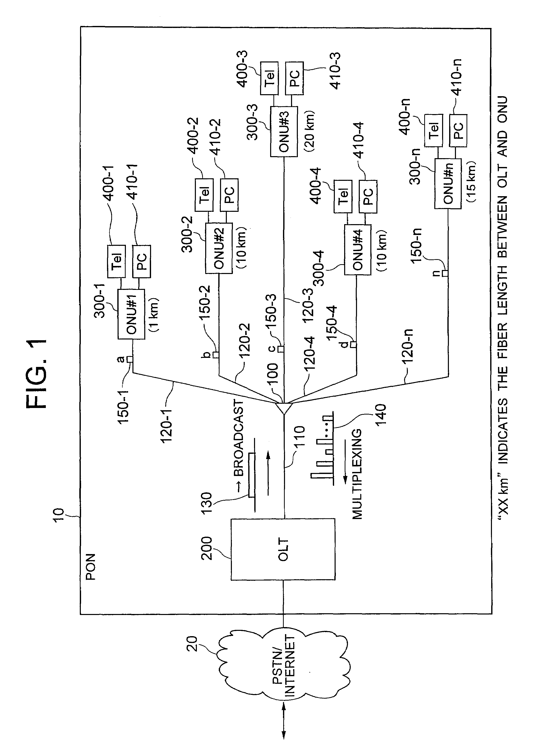
[0032]FIG. 1 shows the configuration of an optical network in which the present invention is applied.

[0033]PON 10 is composed of an optical splitter 100, an OLT 200 being a device on the station side installed in an office building of a telecommunications operator or the like, a trunk fiber 110 connecting OLT 200 and the optical splitter, a plurality of ONUs 300 being subscriber side devices installed inside the respective subscriber residences or in the vicinity thereof, and a plurality of branch fibers 120 respectively connecting optical splitter 100 and a plurality of ONUs 300. OLT 200 can be connected, via trunk fiber 110, optical splitter 100, and branch fibers 120, to e.g. 32 ONUs 300. Also, user terminals such as telephones 400 and Personal Computers 410 are respectively connected to the plurality of ONUs 300. PON 10 is connected via OLT 200 to a PSTN (Public Switched Telephone Network) or the Internet 20 and transmits and receives data to / from external networks.

[0034]In FIG....

second embodiment

[0056]As another embodiment, there may be considered one in which periodic timing generation part 702 periodically generates and outputs, during the ranging window interval, ATC resets and delimiter detection validation signals. Even in this case, it is possible for periodic timing generation part 702, by means of a ranging window signal received from grant generation part 509, to output the aforementioned reset signals and the like periodically just during the ranging window interval.

[0057]In FIG. 9, the time chart of the present embodiment is shown. The signals generated by periodic timing generation part 702 are indicated as ATC resets 902. OLT 200 transmits distance measurement requests (ranging requests) 905 toward ONU 300-1, ONU 300-2, and ONU 300-3, and ONU 300-1, ONU 300-2, and ONU 300-3 respectively transmit distance measurement signals (ranging responses). Specifically, ONU 300-1 transmits a distance measurement signal 910, ONU 300-2 transmits a distance measurement signal...

third embodiment

[0059]In the method of the second embodiment, there is the possibility that an ATC reset and a distance measurement signal from an ONU collide, so at this point, the ranging processing with respect to the ONU would fail. As yet another embodiment, there may be considered a method devised so that each ONU having received a ranging request from OLT 200 replies with a plurality of ranging requests, leaving intervals in between.

[0060]In FIG. 10, the time chart of the present embodiment is shown. Regarding portions which are the same, as in the time chart of FIG. 9, the same reference numerals are attached. A signal generated by periodic timing generation part 702 is shown as ATC reset 902. OLT 200 transmits distance measurement requests (ranging requests) 905 toward ONU 300-1, ONU 300-2, and ONU 300-3. ONU 300-1, ONU 300-2, and ONU 300-3 respectively transmit a plurality of distance measurement signals (ranging responses). Specifically, ONU 300-1 transmits a distance measurement signal ...


PUM


Abstract

A station-side communication device connected to subscriber-side communication devices via an optical combining device; sending, to the subscriber-side communication devices, a distance measurement request signal; computing transmission delay times of optical signals from the individual subscriber-side communication devices by receiving distance measurement signals, and including: a threshold control part identifying the level of distance measurement signals; a signal detection part detecting breaks in the distance measurement signals from the threshold control part; a transmission granting part determining the timing at which transmission of optical signals is granted, and a reset timing generation part that, there is notification of detection of a break in the distance measurement signal from the signal detection part while it is being notified that distance measurement is carried out to and from the subscriber-side communication devices from the transmission granting part, sends a reset signal indicating that the voltage level is reset to the threshold control part.

Description

INCORPORATION BY REFERENCE[0001]The present application claims priority from Japanese application JP2006-279446 filed on Oct. 13, 2006, the content of which is hereby incorporated by reference into this application.BACKGROUND OF THE INVENTION[0002]The present application pertains to a PON (Passive Optical Network) system in which a plurality of subscriber connection devices share an optical transmission line.[0003]As an optical access system, there is known the PON which makes a 1-to-n connection (n being an integer equal to or greater than 2) between an OLT (Optical Line Terminal) arranged on the station side and an ONU (Optical Network Unit) arranged on the subscriber side, by means of a device passively carrying out combining of optical signals, such as an optical splitter. A plurality of ONUs are connected to the terminals (e.g. PCs or the like) of the respective subscribers, the electrical signals from a terminal being converted into optical signals and transmitted toward the O...

Claims


Application Information

Patent Timeline
Patent Type & Authority Applications(United States)
IPC IPC(8): H04J14/00H04B10/07H04B10/077H04B10/27H04B10/272H04L12/44
CPCH04J3/0682H04J3/1694
Inventor KAZAWA, TOHRUOHIRA, MASAKIYAJIMA, YUSUKESAKAMOTO, NORIHIRO
Owner HITACHI LTD
Why Eureka
Try Eureka