
Apparatus for preventing carbon corrosion at cathod in fuel cell

a fuel cell and cathode technology, applied in the direction of functional valve types, electrical generators, transportation and packaging, etc., can solve the problems of increasing the layout of additional devices, increasing the cost of additional devices, so as to prevent carbon corrosion and effectively prevent the corrosion of carbon materials

Inactive Publication Date: 2008-12-25
HYUNDAI MOTOR CO LTD +1
View PDF8 Cites 10 Cited by
  • Summary
  • Abstract
  • Description
  • Claims
  • Application Information

AI Technical Summary

Benefits of technology

[0031]The present invention has been made in an effort to solve the above problems, and an object of the present invention is to provide an apparatus for preventing carbon corrosion at the cathode of a fuel cell, which can effectively prevent the corrosion of a carbon material at the cathode by preventing the formation of hydrogen / oxygen interface at the anode of the fuel cell during startup and shutdown thereof.
[0032]In one aspect, the present invention provides an apparatus for preventing carbon corrosion at the cathode of a fuel cell, the apparatus comprising: an air blower supplying air from an air supply source to a fuel cell; a fuel cell receiving air from the air blower to generate electricity by a chemical reaction; an air discharge pipe through which residual air remaining after oxygen of the air is consumed for chemical reaction in the fuel cell is discharged; a pressure sensor provided in the air discharge pipe for detecting air pressure in the fuel cell; an air discharge solenoid valve provided in the air discharge pipe for controlling air flow of the air discharge pipe; and a controller controlling operation of the air blower and the air discharge solenoid valve by receiving a signal detected by the pressure sensor. The controller detects the air pressure through the pressure sensor to allow the air blower to supply air to the fuel cell until the air pressure reaches a predetermined pressure and then closes the air discharge solenoid valve until the oxygen in the fuel cell is completely exhausted, thereby preventing the formation of hydrogen / oxygen interface at the anode of the fuel cell.
[0035]In still another preferred embodiment, the air discharge solenoid valve is equipped with a hot wire for preventing the air discharge solenoid valve from being frozen due to water when the temperature drops below zero.
[0036]In yet another preferred embodiment, the water discharge solenoid valve is equipped with a hot wire for preventing the air discharge solenoid valve from being frozen due to water when the temperature drops below zero.
[0037]In a further preferred embodiment, an air supply solenoid valve is provided between the air blower and the fuel cell to minimize the amount of air to be consumed for chemical reaction in the fuel cell, thereby reducing the time for which the cathode is filled with nitrogen.

Problems solved by technology

However, using the gas burner has a safety problem and requires an additional device.
Such an additional device requires much power and space in terms of layout.
Also, using the nitrogen bomb has some problems in that it requires an additional device for mounting the nitrogen bomb in the vehicle and it is necessary to refill the nitrogen bomb when the nitrogen is exhausted.
In addition, purging air during the fuel cell shutdown process, the hydrogen / oxygen interface is inevitably formed at the anode and the hydrogen / oxygen interface shortens the time for which the anode is filled with air, thus degrading the performance of the fuel ell.
Moreover, in the apparatus and method of using the fuel cell startup / shutdown process, it takes much time for startup and shutdown, which results in a problem of inconvenience.
Accordingly, the prior art apparatuses and methods have adverse effects on the durability performance of the fuel cell.
Furthermore, if the hydrogen exhaust and the air exhaust are exposed to the air, there is a possibility of causing damage to the fuel cell due to pollutants in the ambient air.

Method used


Image

  • Apparatus for preventing carbon corrosion at cathod in fuel cell
  • Apparatus for preventing carbon corrosion at cathod in fuel cell
  • Apparatus for preventing carbon corrosion at cathod in fuel cell

Examples


Embodiment Construction

[0069]Reference will now be made in detail to the preferred embodiment of the present invention, examples of which are illustrated in the drawings attached hereinafter, wherein like reference numerals refer to like elements throughout. The embodiments are described below so as to explain the present invention by referring to FIGS. 3-7.

[0070]As discussed above, the prior art has the following problems: 1) complicated structure (resistance, hydrogen burner in hydrogen recirculation line, nitrogen tank, etc.); 2) excessive time required by the complicated startup / shutdown process; 3) degradation of durability performance due to air flowing into the anode during startup / shutdown by employing an additional device; and 4) degradation of durability performance due to fuel cell pollutants by the hydrogen exhaust and air exhaust exposed to the air.

[0071]For example, the moisture in the fuel cell may be evaporated under dry atmospheric conditions and the humidifying water of an MEA is evapora...


PUM


Abstract

The present invention provides an apparatus for effectively preventing carbon corrosion from occurring at the cathode of a fuel cell. The present apparatuses include an air blower supplying air from an air supply source to a fuel cell; a fuel cell receiving air from the air blower to generate electricity by a chemical reaction; an air discharge pipe through which residual air remaining after oxygen of the air is consumed for chemical reaction in the fuel cell is discharged; a pressure sensor provided in the air discharge pipe for detecting air pressure in the fuel cell; an air discharge solenoid valve provided in the air discharge pipe for controlling air flow of the air discharge pipe; and a controller controlling operation of the air blower and the air discharge solenoid valve by receiving a signal detected by the pressure sensor wherein the controller detects the air pressure through the pressure sensor to allow the air blower to supply air to the fuel cell until the air pressure reaches a predetermined pressure and then closes the air discharge solenoid valve until the oxygen in the fuel cell is completely exhausted, thereby preventing the formation of hydrogen / oxygen interface at the anode of the fuel cell.

Description

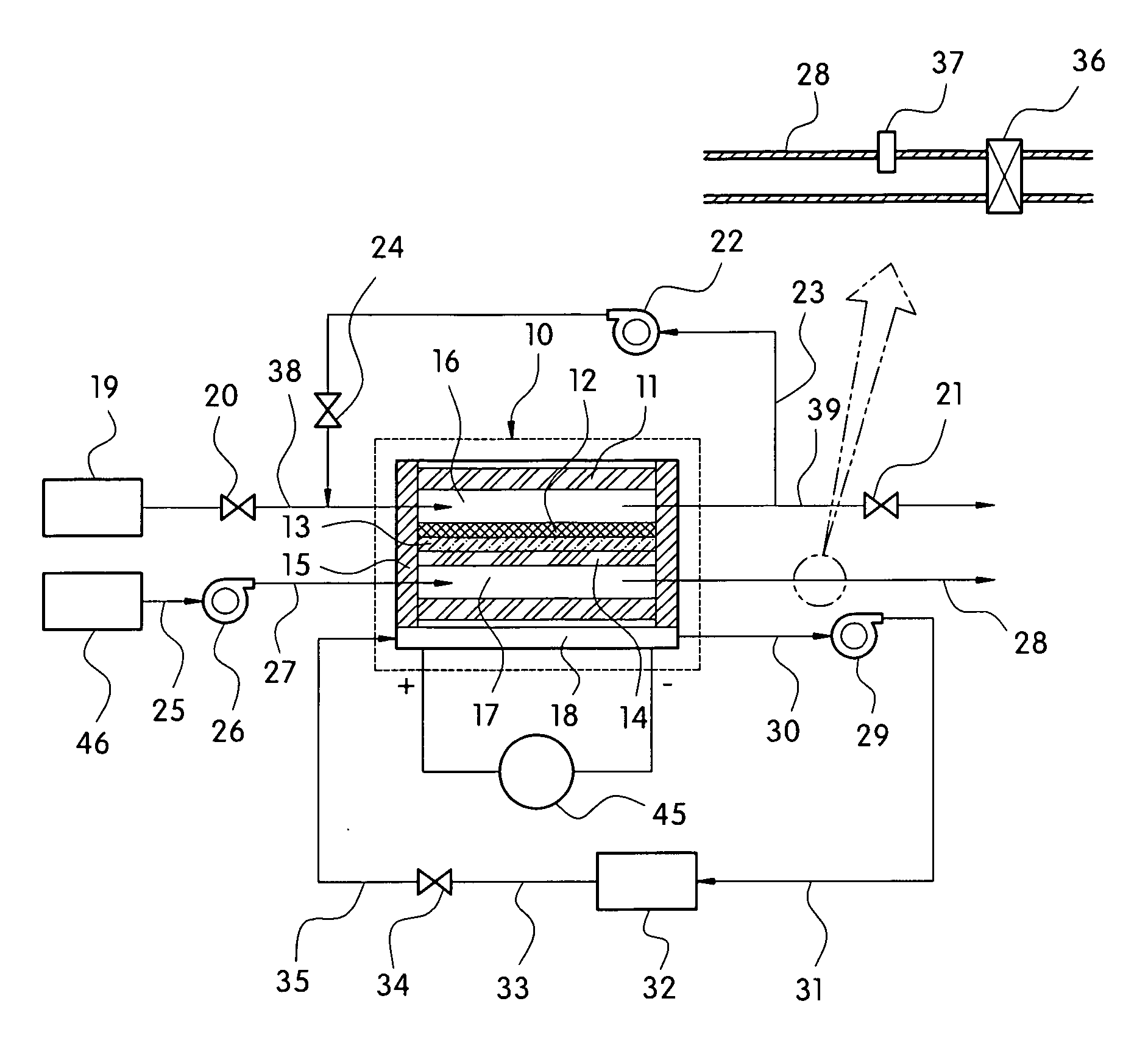
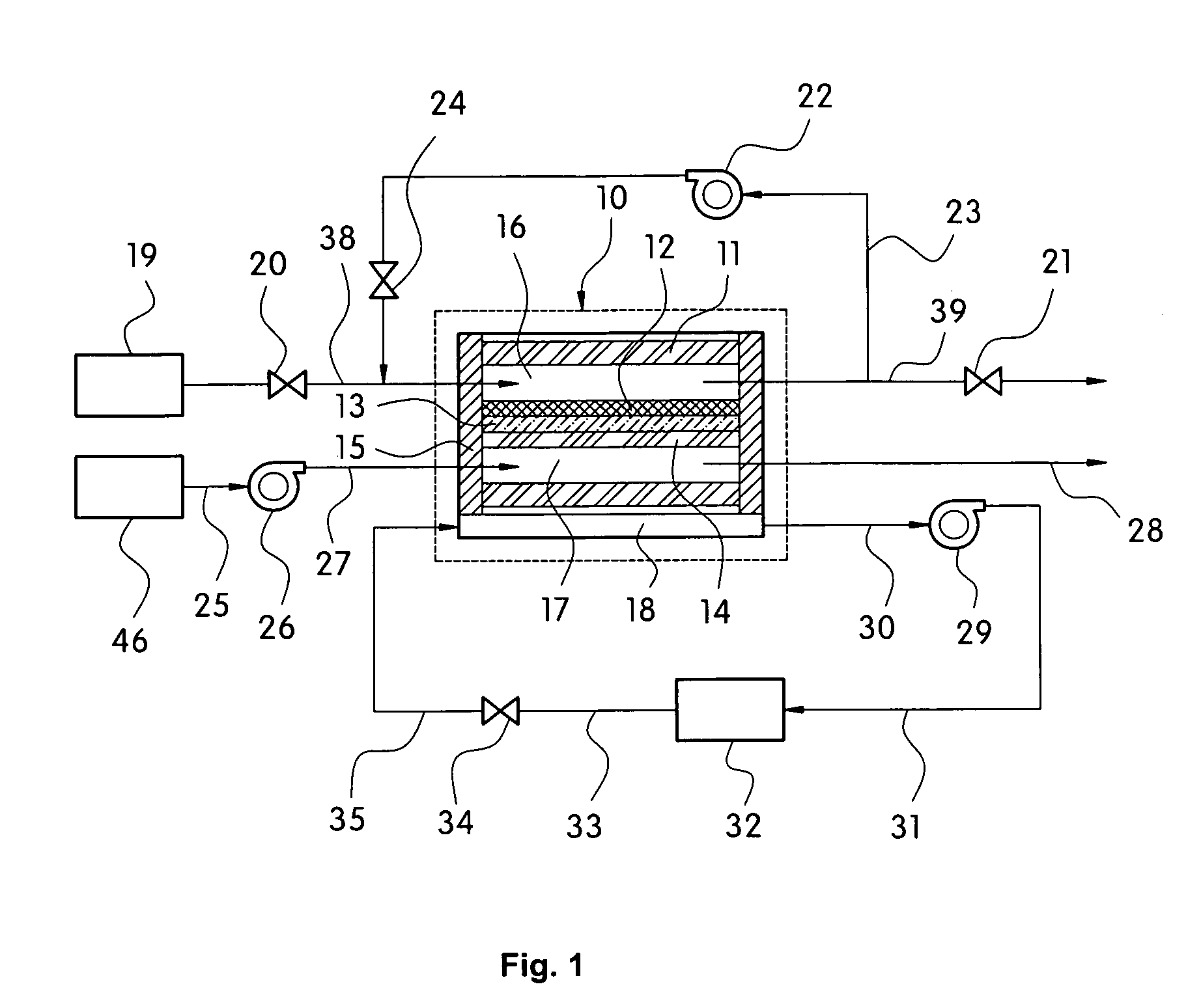
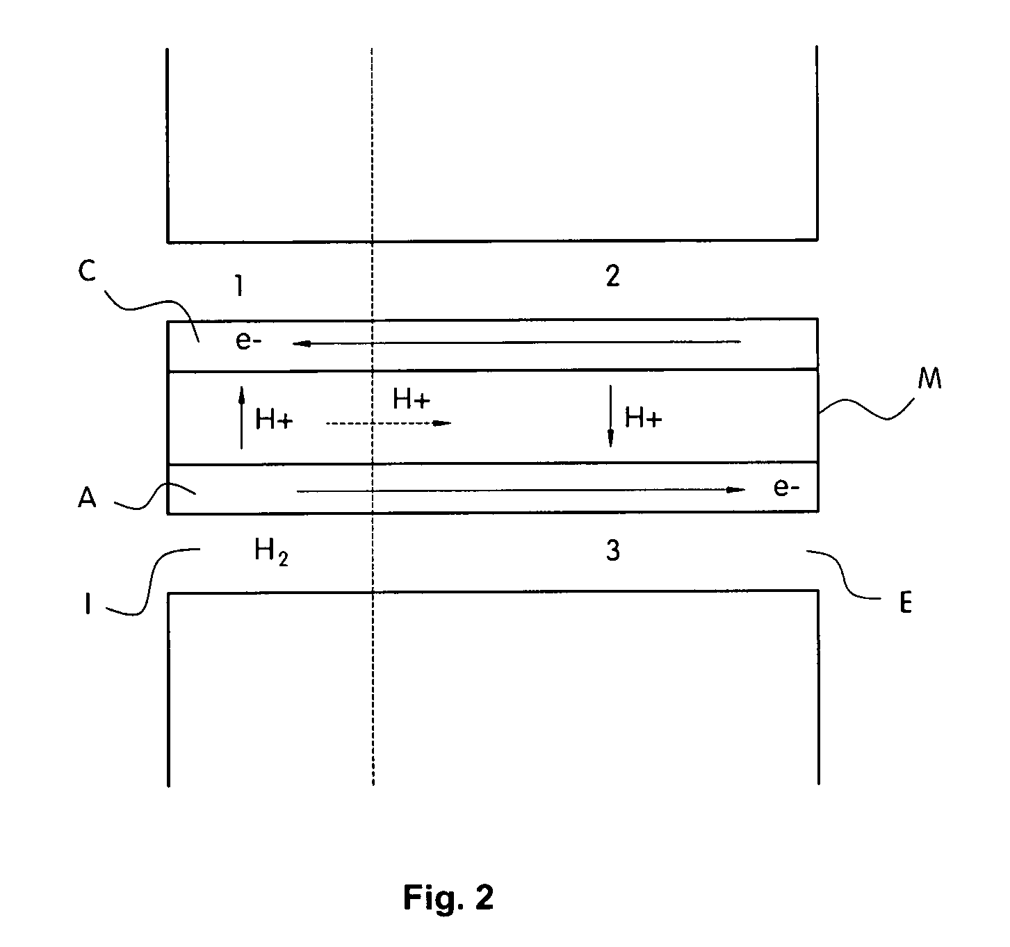
CROSS-REFERENCE TO RELATED APPLICATION[0001]This application claims the benefit under 35 U.S.C. §119(a) on Korean Patent Application No. 10-2007-0060912, filed on Jun. 21, 2007, the entire contents of which are incorporated herein by reference.BACKGROUND[0002](a) Technical Field[0003]The present invention relates to an apparatus for preventing carbon corrosion at the cathode of a fuel cell by preventing formation of hydrogen / oxygen interface at the anode of the fuel cell during startup and shutdown of the fuel cell.[0004](b) Background Art[0005]A fuel cell used as a main power source of a fuel cell vehicle generates electricity by reaction of oxygen supplied from air with hydrogen stored in a fuel tank of the vehicle.[0006]FIG. 1 is a schematic diagram of a fuel cell system in a fuel cell vehicle. The fuel cell 10 includes a separator 11, an anode 12, an electrolyte membrane 13, a cathode 14, a hydrogen / oxygen / coolant distribution structure 15, an anode flow field 16, a cathode flow...

Claims


Application Information

Patent Timeline
IPC IPC(8): H01M8/04
CPCH01M8/04089H01M8/0441H01M8/04753H01M8/04761Y10T137/7837Y02E60/50H01M8/04H01M8/06
Inventor OH, SEUNG CHANLEE, JONG HYUNYOON, JONG JINKO, JAE JUNKIM, YOUNG MINSON, IK JAE
Owner HYUNDAI MOTOR CO LTD
Learn More