Method of machining substrate

a substrate and machining technology, applied in the direction of grinding drives, manufacturing tools, lapping machines, etc., can solve the problems of warping of wafers and breaking of wafers

Active Publication Date: 2008-12-25
DISCO CORP
View PDF8 Cites 12 Cited by
  • Summary
  • Abstract
  • Description
  • Claims
  • Application Information

AI Technical Summary

Benefits of technology

[0009]Accordingly, it is an object of the present invention to provide a method of machining a substrate provided at its face-side surface with an appendant part including protruding metals and a resin part, by cutting the appendant part, grinding the back-side surface of the substrate and removing the resin part of the appendant part so as to obtain a substrate in which the protruding metals are protruding on the face side of the substrate, wherein the thickness of the substrate per se and the heights of the protruding metals are made uniform, the total thickness of the substrate is also made uniform and, as a result, an enhanced dimensional accuracy can be achieved.
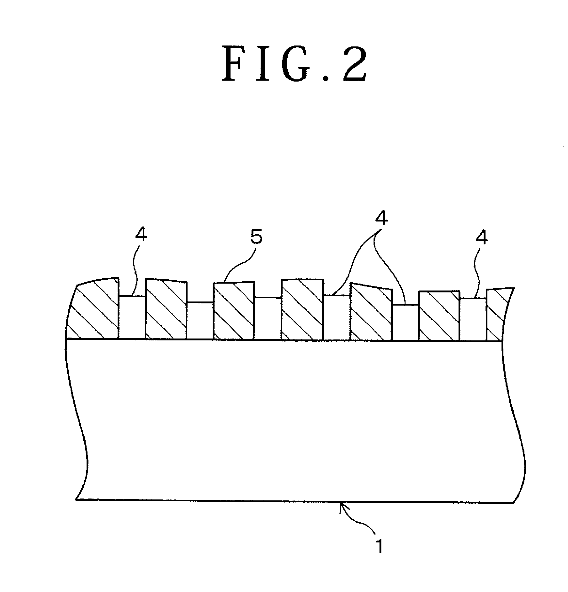
[0011]According to the first aspect of the present invention, the surface of the appendant part cut in the appendant part cutting step in the beginning is in the condition where top parts of the protruding metals are exposed and their surroundings are filled with the resin part, and the protruding metals and the resin part are flush with each other, i.e., the appendant part surface is machined to be flat. Since the back-side surface of the substrate is sucked directly onto the suction surface of the suction table without any protective tape or the like therebetween, the thickness of the appendant part can adequately be brought to the desired height by cutting, without being influenced by a protective tape or the like. Therefore, at this stage, the protruding metals can be made uniform in height.
[0012]In the next back-side surface grinding step, the surface of the appendant part machined to be flat is sucked directly onto the suction surface of the suction table to hold the substrate, and the back-side surface of the substrate is ground. Here, since the surface of the appendant part is sucked directly onto the suction surface of the suction table without any protective tape or the like therebetween, the thickness of the substrate can be adequately ground to the desired height, without being influenced by a protective tape or the like; therefore, the thickness of the substrate can be made uniform. In the back-side surface grinding step, though the protruding metals make contact with the suction surface of the suction table, the surrounding resin part also makes contact with the suction surface, so that the machining load during the grinding is dispersed to the resin part side. This ensures that the top parts of the protruding metals can be restrained from being damaged. When the resin part of the appendant part is removed in the final resin part removing step, a substrate can be obtained in which the protruding metals being uniform in height are protruding on the face side of the substrate which is uniform in thickness. Naturally, the total thickness of the substrate is uniform.
[0014]In the second aspect of the present invention, a machining method is provided which is the same as that of the first-named invention, except that the appendant part cutting step is divided into the first appendant part cutting step of cutting only the surface of the resin part of the appendant part in such a range as not to reach the protruding metals, and the second appendant part cutting step of simultaneously cutting the protruding metals and the resin part until the tips of the protruding metals and the resin part become at least flush with each other. In the back-side surface grinding step, only the resin part of the appendant part cut in the first appendant part cutting step is sucked onto the suction table, so that the protruding metals are in the state of being protected by the resin part and, hence, do not make contact with the suction table. Therefore, there is no risk of damaging or staining the protruding metals at the time of grinding the back-side surface. The appendant part is cut to the desired thickness in the second appendant part cutting step, and the resin part is removed in the final resin part removing step, to obtain a substrate in which the protruding metals are protruding from the face-side surface of the substrate. According to this invention, the back-side surface of the substrate and the surface of the appendant part are sucked directly onto the suction surface of the suction table without any protective tape or the like therebetween in the relevant steps, so that the height of the appendant part and the thickness of the substrate can adequately be brought to the respective desired values by cutting. Therefore, it is possible to obtain a substrate in which the thickness of the substrate and the height of the protruding metals are uniform, and which has a uniform total thickness.
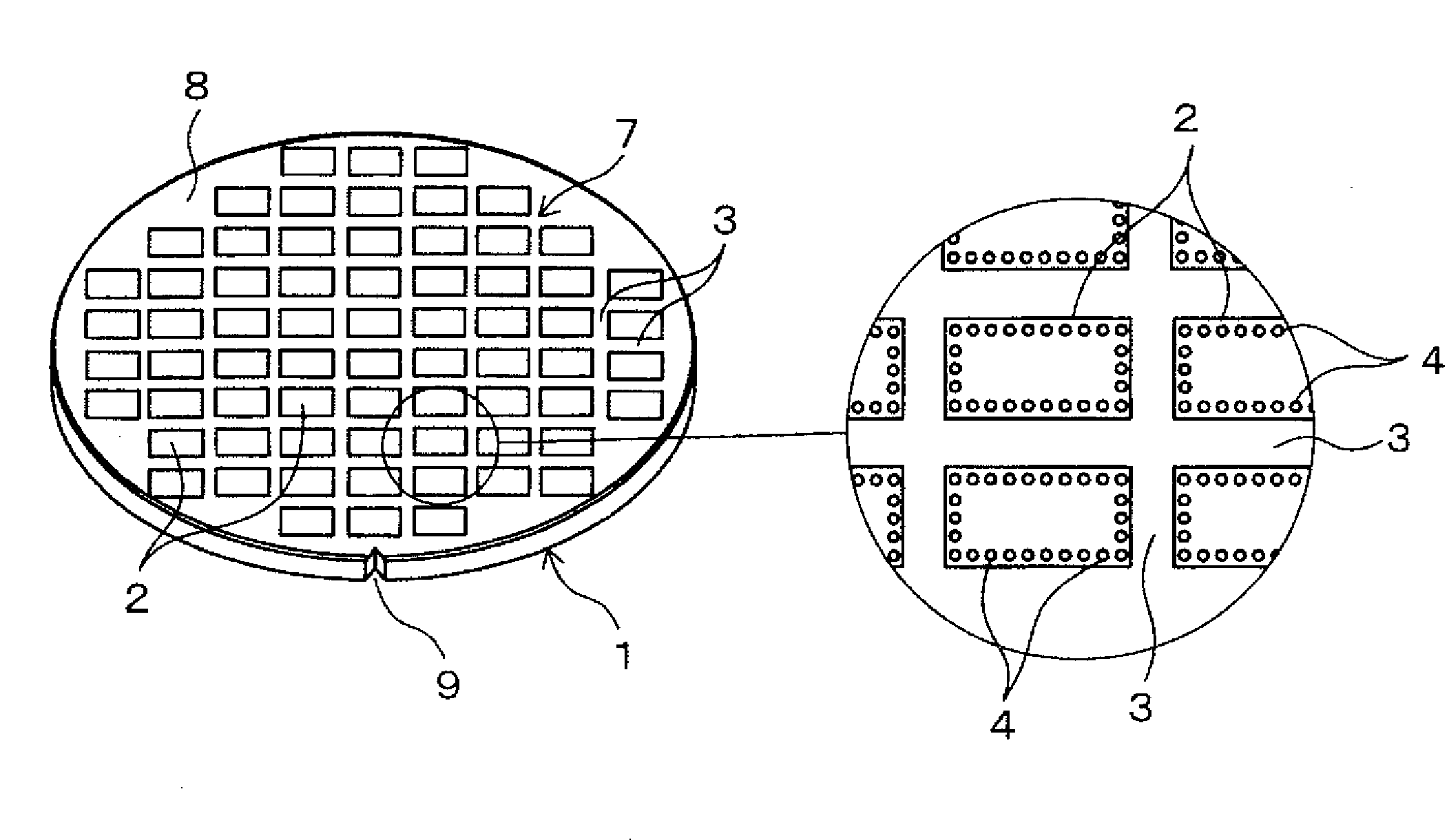
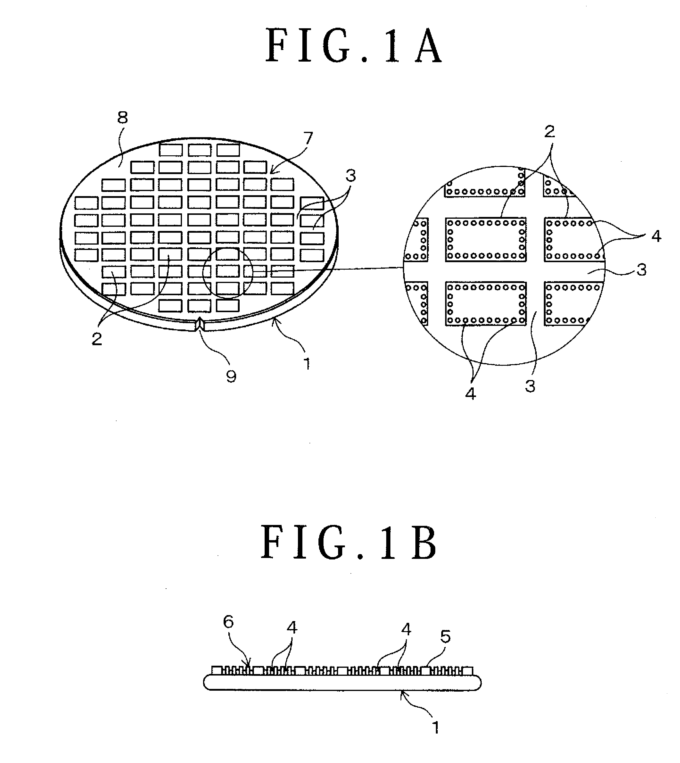
[0015]In each of the first and second aspects of the present invention, preferably, the face-side surface of the substrate is provided with a device formation region and an outer peripheral marginal region surrounding the device formation region. Also, preferably, only that region of the back-side surface which corresponds to the device formation region is ground in the back-side surface grinding step. This mode ensures that the substrate obtained upon the grinding of the back-side surface has been thinned only in the device formation region, and the outer peripheral marginal region surrounding the device formation region is left in the original thickness so as to form an annular projected part. The annular projected part secures the rigidity of the substrate, promises easy handleability of the substrate thinned upon the grinding of the back-side surface, and prevents the substrate from being damaged.
[0016]According to the present invention, in the process in which a substrate provided at its face-side surface with an appendant part including protruding metals and a resin part is subjected to cutting of the appendant part, grinding of the back-side surface of the substrate, and removal of the resin part of the appendant part to obtain a substrate having the protruding metals protruding from the face-side surface of the substrate, the thickness of the substrate per se and the height of the protruding metals can be made uniform, the total thickness of the substrate can be made uniform and, as a result, an enhanced dimensional accuracy can be achieved.

Problems solved by technology

In addition, since the wafer 1 is thinned by grinding its back-side surface before forming the electrodes 4, there would be a problem, in the case where the desired thickness of the wafer 1 is comparatively small, that the wafer 1 may be warped in the step of forming the electrodes by plating after the thinning or that the wafer 1 may be broken in the subsequent step of cutting the appendant part 6.

Method used


Image

  • Method of machining substrate
  • Method of machining substrate
  • Method of machining substrate

Examples


first embodiment

[2] Method of Machining Wafer in First Embodiment

[0037][2-1] Appendant Part Cutting Step

[0038]FIG. 3A shows a wafer 1 similar to that shown in FIGS. 1A and 1B. First, a cutting step is carried out to cut the surface of the appendant part 6 of the wafer 1 to uniformly adjust the height of the electrodes 4. In this case, the appendant part 6 to be cut is tip parts of all the electrodes 4 and the resist layer 5, and the cutting is conducted until they become flush with each other and the electrodes 4 come to have the desired height.

[0039]For the cutting, a cutting apparatus 10 shown in FIG. 5 is used preferably. According to the cutting apparatus 10, the back-side surface of the wafer 1 is sucked directly onto a suction surface of a vacuum chuck type chuck table (suction table) 20 to hold the wafer 1, and a tool 37 of a cutting unit 30 being rotated is pressed against the appendant part 6, whereby the surface of the appendant part 6 is cut. FIG. 3B shows the wafer 1 in the state in the...

second embodiment

[3] Method of Machining Wafer in Second Embodiment

[0068]Now, a method of machining a wafer according to a second embodiment of the present invention will be described below referring to FIG. 8. In the second embodiment, an appendant part cutting step is divided into a first appendant part cutting step of cutting only the surface of a resist layer 5 of an appendant part 6 in such a range as not to reach electrodes 4, and a second appendant part cutting step of cutting both the tips of the electrodes 4 and the resist layer 5 to make them flush with each other. Besides, a back-side surface grinding step is carried out between the first cutting step and the second cutting step. In conducting the cutting and the grinding, the above-mentioned cutting apparatus 10 and grinding apparatus 50 are used.

[0069][3-1] First Appendant Part Cutting Step

[0070]FIG. 8A shows a wafer 1 similar to that shown in FIGS. 1A and 1B. First, the back-side surface of the wafer 1 is sucked directly onto a suction...


PUM

PropertyMeasurementUnit
heightaaaaaaaaaa
thicknessaaaaaaaaaa
thicknessaaaaaaaaaa

Abstract

A method of machining a wafer is disclosed, in which the wafer is held by sucking its back-side surface directly onto a suction surface of a chuck table, and the tips of protruding electrodes and a resist layer are cut to make them flush with each other (appendant part cutting step). Next, the wafer is held by sucking the surface of the cut appendant part directly onto the suction surface of the chuck table, and the back-side surface of the wafer is ground (back-side surface grinding step), followed by removing the resist layer. The wafer is held onto the chuck table without using any protective tape but by directly holding the wafer, whereby the wafer can be ground to have a uniform thickness.

Description

BACKGROUND OF THE INVENTION[0001]1. Field of the Invention[0002]The present invention relates to a method of machining a substrate such as a semiconductor wafer provided at its face-side surface with an appendant part including protruding metals and a resin part, in which the appendant part is cut and the back-side surface of the substrate is ground to make the substrate thinner.[0003]2. Description of the Related Art[0004]The flip flop technology has been known as one of mounting technologies for the purpose of suppressing the volume needed to mount a semiconductor chip onto a wiring substrate or for the purpose of realizing a higher transfer speed of electrical signals. The flip flop technology includes forming protruding electrodes having a height of, for example, about 15 to 100 μm on a surface of a semiconductor chip, and bonding the electrodes directly to electrodes provided on the mounting substrate side. The protruding electrodes are formed by plating or the like method, and...

Claims


Application Information

Patent Timeline
Patent Type & Authority Applications(United States)
IPC IPC(8): B26D9/00B24B1/00
CPCB24B37/04Y10S438/959H01L21/67219H01L21/6838H01L24/11H01L24/94H01L2224/1147H01L2224/1184H01L2224/13099H01L2224/94H01L2924/01078H01L2924/01082H01L2924/10158H01L21/304H01L2924/00011H01L2924/00014Y10T83/0524H01L2924/01005H01L2924/01006H01L2924/01023H01L2924/01033H01L2224/11H01L2224/03H01L2224/0401
Inventor KIMURA, YUSUKEDAII, TOSHIHARUMORI, TAKASHI
Owner DISCO CORP
Why Eureka
Try Eureka