Water rocket engine with a two-phase nozzle

a water rocket and nozzle technology, applied in waterborne vessels, water-based vessels, propellant elements, etc., can solve the problems of unfulfilled need to continually improve, and achieve the effect of improving rocket performance, range and equivalent exhaust velocity

Inactive Publication Date: 2009-01-01
KING FAHD UNIVERSITY OF PETROLEUM AND MINERALS
View PDF21 Cites 2 Cited by
  • Summary
  • Abstract
  • Description
  • Claims
  • Application Information

AI Technical Summary

Benefits of technology

[0010]Size, distribution and location of the inlet water holes determine the water to gas mass flow ratio. The water droplets are accelerated via drag force genera

Problems solved by technology

Yet, there remains an unfulfilled need to continually improve water rocket pe

Method used


Image

  • Water rocket engine with a two-phase nozzle
  • Water rocket engine with a two-phase nozzle

Examples


Embodiment Construction

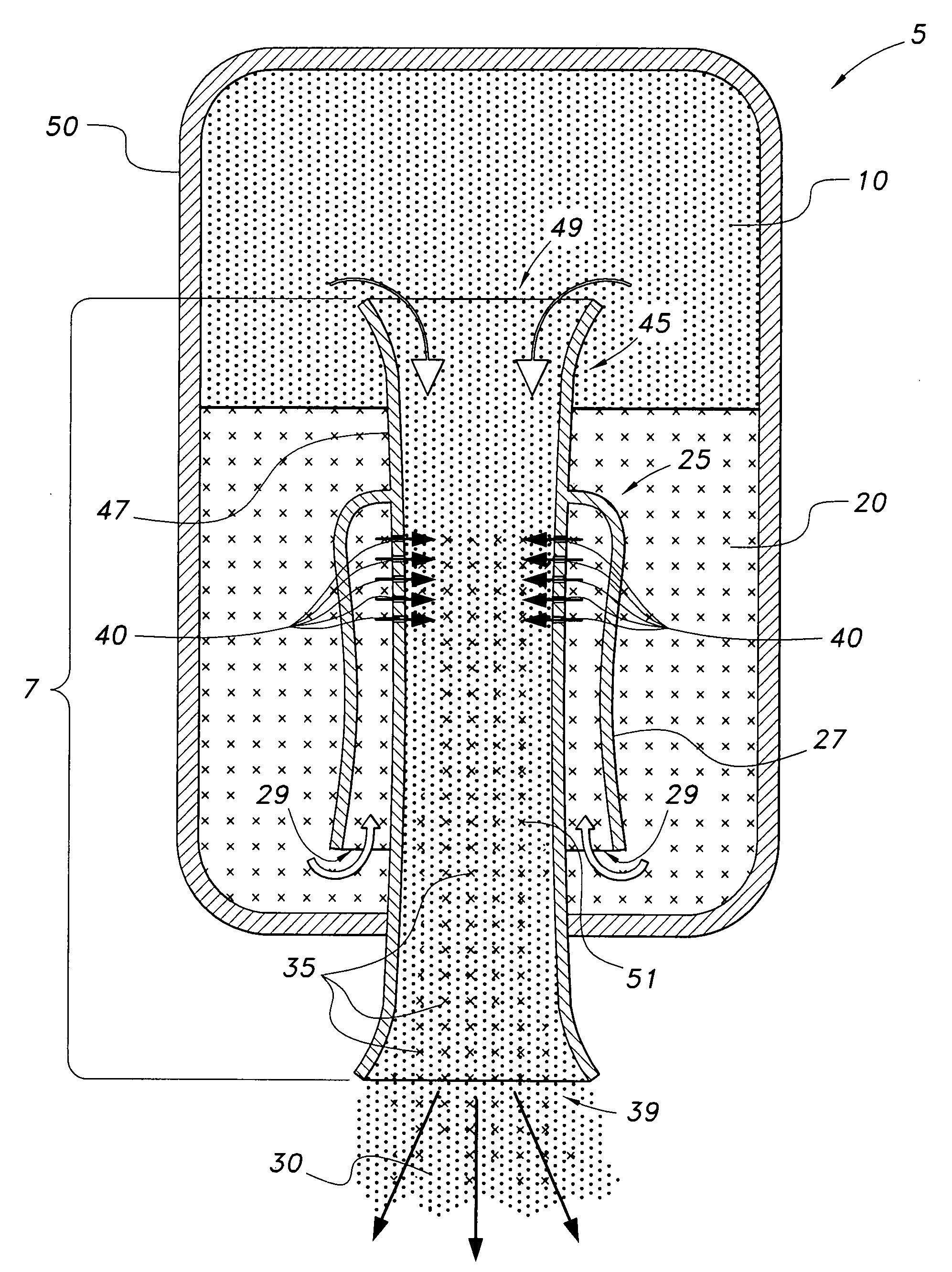
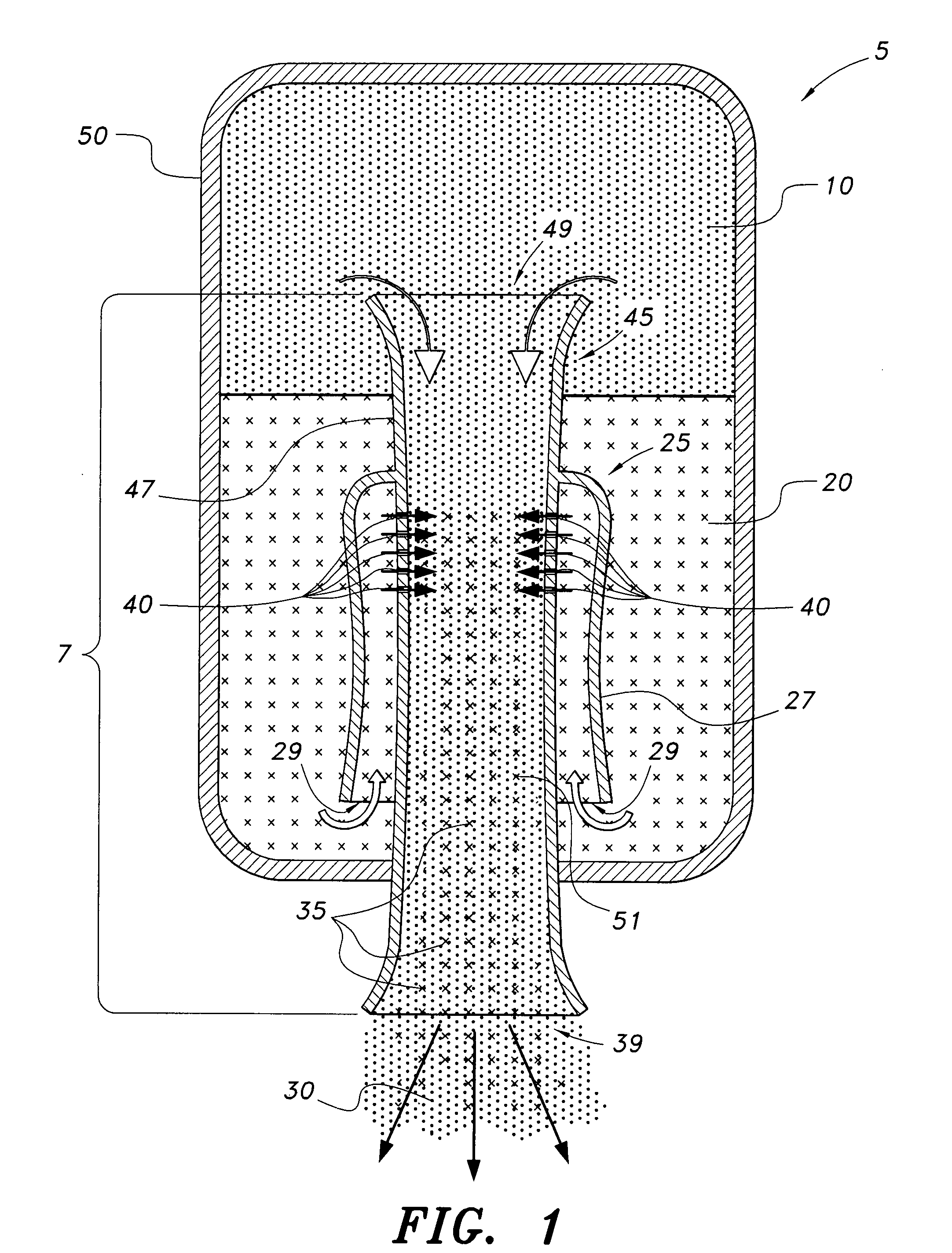
[0014]As shown in FIG. 1, the present invention is a water rocket propulsion system 5 having a reservoir 50, and a nozzle assembly 7 disposed along a central longitudinal axis therein, the nozzle assembly 7 comprising an inverted cup shaped fluid capture vessel 25 having a substantially concave sidewall 27 and concentrically extending from an elongated tube 45. Open lower portion of the fluid capture vessel forms a fluid inlet 29.

[0015]The elongated tube has a concave shaped side wall 47 that forms a nozzle gas inlet 49 at an upper portion of the tube, a nozzle outlet 39 at a lower portion of the tube, and a passageway 51 disposed between the tube upper portion and the tube lower portion. Within the confines of the capture vessel 25, fluid injection holes 40 are disposed in the tube sidewall 47 to provide fluid intake into the nozzle passageway 51 where fluid 20 and gas 10 combine to form a two phase propellant 30.

[0016]During operation of the propulsion system the combined propella...


PUM


Abstract

The water rocket engine with a two-phase nozzle includes a water rocket propulsion system having a reservoir, and a nozzle assembly disposed along a central longitudinal axis therein, the nozzle assembly comprising an inverted cup shaped fluid capture vessel having a substantially concave sidewall and extending away from an elongated tube. Open lower portion of the fluid capture vessel forms a fluid inlet. The elongated tube has a concave shaped side wall that forms a nozzle gas inlet at an upper portion of the tube, a nozzle outlet at a lower portion of the tube, and a passageway disposed between the tube upper portion and the tube lower portion. Within the confines of the capture vessel, fluid injection holes are disposed in the tube sidewall to provide fluid intake into the nozzle passageway where fluid and gas combine to form a two phase propellant.

Description

BACKGROUND OF THE INVENTION[0001]1. Field of the Invention[0002]The present invention relates to a liquid-vapor gas motor and nozzle. More specifically, it is directed to a two phase reservoir and nozzle that, when sufficiently pressurized, can be used to propel a vehicle such as, e.g., a boat, plane, rocket, and the like, by a liquid / air propulsion combination.[0003]2. Description of the Related Art[0004]Over the years various types of water rockets have been developed which rely upon thrust developed from the expulsion of pressurized liquid and / or pressurized gases from a projectile in order to propel the vehicle. For example, in conventional water rockets the water acts as the propellant, while compressed gas is used as the energy source. Propulsion force is provided initially by the accelerated water through the nozzle, the water being driven by the high pressure of the gas acting on the top surface of the fluid. Once the fluid is exhausted, the gas exits the nozzle to thereby a...

Claims


Application Information

Patent Timeline
IPC IPC(8): F02K5/00
CPCF02K9/62F02K9/42
Inventor AL-OUTUB, AMRO MOHAMMADTALEB, JAD
Owner KING FAHD UNIVERSITY OF PETROLEUM AND MINERALS
Why Eureka
Try Eureka