Regenerator matrix with mixed screen configuration

a technology of a generator and a matrix, which is applied in the direction of indirect heat exchangers, refrigeration components, lighting and heating apparatus, etc., can solve the problems of degrading the performance of the cooler, affecting the operation of the cooler, so as to achieve a large void volume

Inactive Publication Date: 2009-01-01
FLIR SYST INC
View PDF13 Cites 6 Cited by
  • Summary
  • Abstract
  • Description
  • Claims
  • Application Information

AI Technical Summary

Benefits of technology

[0024]A regenerator matrix 215 is disposed along the longitudinal axis 158 to substantially fill the hollow tube 152 and exchanges thermal energy with the fluid as the fluid passes through the fluid conduit from the hot end to the cold end and back from the cold end to the hot end. In particular, the regenerator matrix 215 is configured to vary a fluid flow resistance and a capacity for convective heat transfer with the fluid along the longitudinal axis 158.
[0025]In particular, the regenerator matrix 215 includes three portions 235, 210 and 230. Each portion 235, 210 and 230 is made from a plurality of individual screen elements 50 stacked together. Alternately, each portion is made from a plurality of composite regenerator elements 110 stacked together. In this case, each composite regenerator element 110 is made from a plurality of individual screen elements 50 sintered together in a stack. A first portion 235 of the regenerator matrix 215 is disposed proximate to the hot end of the regenerator piston 200. A second portion 210 of the regenerator matrix 215 is disposed proximate to the cold end of the regenerator piston 200. A third portion 230 of the regenerator matrix 215 is disposed between the first portion 235 and the second portion 210. The first portion 235 is configured with the lowest flow resistance and convective thermal energy transfer capacity and includes individual screen elements having a large void volume and a small wire surface area. In particular, each individual screen element of the first portion 235 includes wires having a wire diameter of 0.0021 inches disposed at a pitch of 200 wires per inch. The third portion 230 is configured with an intermediate flow resistance and convective thermal energy transfer capacity and includes individual screen elements having an intermediate void volume and wire surface area. In particular, each individual screen element of the third portion 230 includes wires having a wire diameter of 0.0014 inches disposed at a pitch of 325 wires per inch. The second portion 210 is configured with the highest flow resistance and convective thermal energy transfer capacity and includes individual screen elements having a small void volume and small wire surface area. In particular, each individual screen element of the second portion 210 includes wires having a wire diameter of 0.0012 inches disposed at a pitch of 400 wires per inch.

Problems solved by technology

The metal screens offer good convective thermal energy transfer between the working fluid and the matrix material, however, excessive thermal conductivity of the matrix configuration along an axis between the hot end and the cold end can create a thermal short circuit, which transfers thermal energy directly from the hot end to the cold end by conduction.
This degrades the performance of the cooler.
However, an excessive compacting force increases thermal conductivity between screens and a thermal short along the stack longitudinal axis allows thermal energy flow directly from the hot end to the cold end by conduction through the compressed screens.
It is a general problem with conventional regenerator matrix configurations, such as the one described above, that the screen elements are extremely fragile.
Any screen element installed into the tube 15 in a non-flat condition can adversely affect the regenerator performance and because there are so many elements, it is difficult to assemble a regenerator matrix entirely of flat screen elements.
As a result, the performance of a conventional regenerator varies in proportion to the number of damaged screens and this leads to an uncertainty about regenerator performance from unit to unit and can lead to a complete regenerator failure.
Non-flat screens reduce screen-packing density; leave excess voids between screens and causes excess void space at the regenerator tube wall.
It is another problem that due to the nature of the regenerator operation, it has been very difficult to determine whether an assembled regenerator will meet its thermal exchange performance requirements.
If the generator fails to meet predetermined performance criteria, it must be replaced or reworked.
As a result, an unacceptable yield of finished cryocoolers occurs.
This adds cost to the manufacturing process.
It is a further problem in the art that assembling many hundreds of individual screens into a regenerator tube is tedious and labor intensive.
A conventional regenerator as described above is tedious and painstaking to assemble and the assembly labor accounts for a significant percentage of the overall manufacturing cost.
It is another problem of the conventional regenerator matrix described above that the mechanical compacting force for compacting the screen elements in the tube is difficult to control.
Excessive compacting causes a thermal short along a longitudinal axis of the stack while insufficient compacting leaves voids in the stack and reduces the number of screen elements in the matrix.
Both conditions degrade performance.
However, non-flat screens or screens hung up by the regenerator tube inner wall result in excess voids that reduce the pressure pulse and decrease the matrix capacity.
It is a still further problem with conventional regenerator elements that the size and shape of each element may vary due to unavoidable tolerances of the element forming process.
Oversized screen diameters cause screens to hang up on the tube wall during insertion and this causes excess void volume.
Excess void volume causes heat exchange and flow rate variations from unit to unit that can adversely affect the performance of a finished cryocooler.
The problems identified above cause a regenerator matrix to perform in an unpredictable manner and the acceptance of the matrix performance is not determined until it is tested in a finished cryocooler.
As a result, the yield of finished cryocoolers in a production environment is adversely impacted.
These shortcomings results in an undesirable manufacturing cost for the product.

Method used


Image

  • Regenerator matrix with mixed screen configuration
  • Regenerator matrix with mixed screen configuration
  • Regenerator matrix with mixed screen configuration

Examples


Embodiment Construction

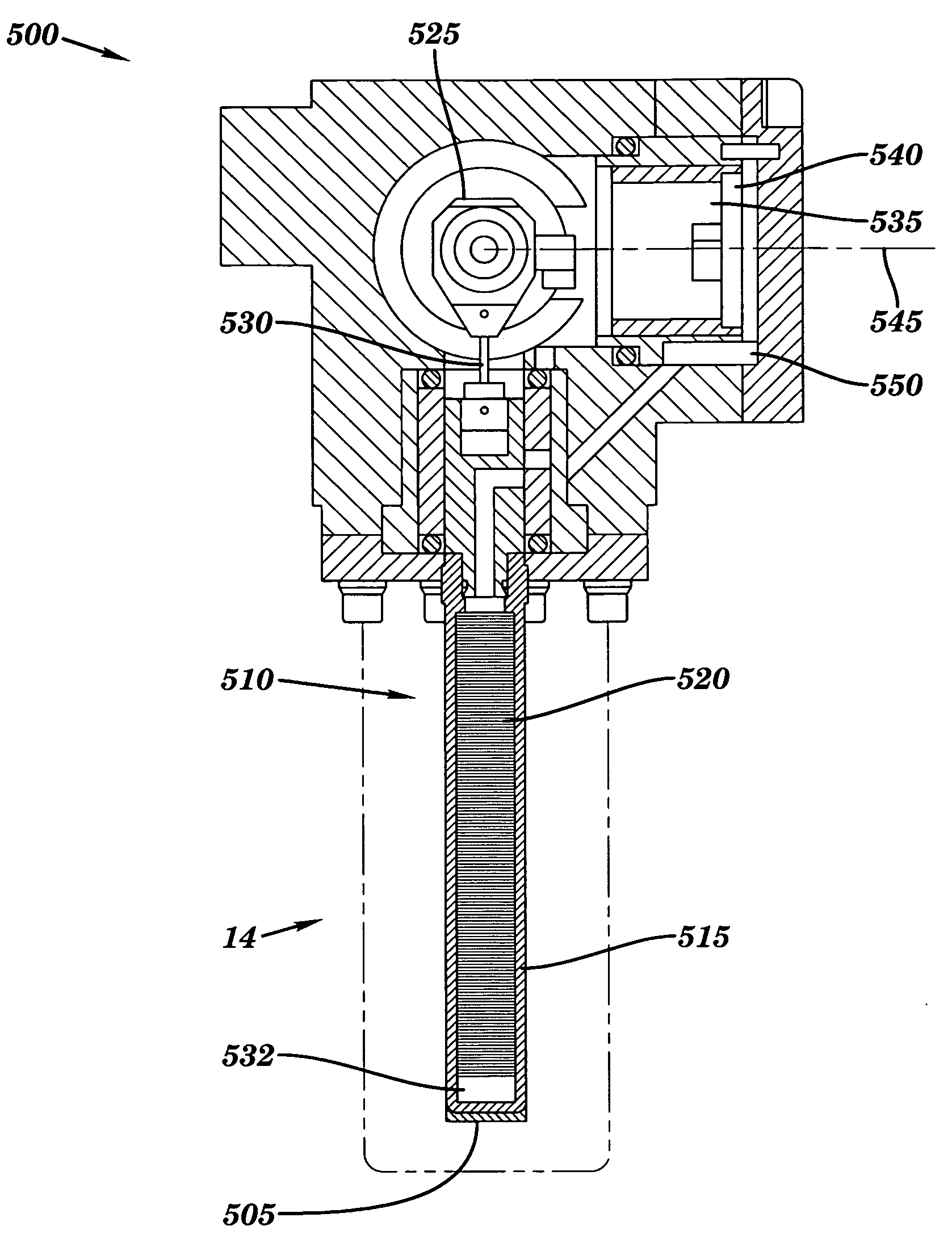
[0043]The preferred embodiments of the present invention are illustrated in the accompanying detailed description and drawings. FIG. 3 depicts a cross-sectional view of a Stirling cycle cryocooler 500 used for cooling components to cryogenic temperatures, e.g. to less than about 135° K. or more particularly to less than about 80° K. FIG. 3 shows an element to be cooled 505 attached to the cold end of a cold well assembly 510. The cold well 510 comprises a thin walled cylindrical cold well tube 515, sealed at a cold end thereof and a cylindrical regenerator piston 520 movably supported within the cold well tube 510. A drive coupling 525 reciprocates the regenerator piston 520 with respect to the cold well tube 515 through a link 530. When the regenerator piston 520 is at the top of its motion cycle, a small volume at the sealed end of the cold well tube 515 provides the expansion space 532 in which an isothermic expansion of the refrigeration gas inside the cold well occurs.

[0044]A c...


PUM


Abstract

A regenerator matrix 215 disposed in a fluid conduit 152 for exchanging thermal energy with a fluid passing through the fluid conduit. The regenerator matrix 215 has a variable fluid flow resistance and a variable capacity for convective heat transfer with the fluid along it longitudinal length. Preferably, the flow resistance and the capacity for convective heat transfer between the fluid and the regenerator matrix each increase as the fluid flows from a hot end to a cold end of the fluid conduit 152. The regenerator matrix 215 is formed from individual screen elements 50 or from stacks of screen elements sintered together as composite regenerator elements 110. A first portion 235 of the regenerator matrix made from first individual screen elements is disposed at the hot end of the regulator matrix 215. A second portion 210 of the regenerator matrix made from second individual screen elements is disposed at the cold end of the regulator matrix. A third portion 230 of the regenerator matrix made from third individual screen elements is disposed between the first portion 235 and the second portion 210. The first portion 235 has the lowest flow resistance and convective thermal energy transfer capacity, the second portion has the highest flow resistance and convective thermal energy transfer capacity, and the third portion has an intermediate flow resistance and convective thermal energy transfer capacity.

Description

CROSS REFERENCE TO RELATED APPLICATIONS[0001]This application is a divisional application and claims priority under 35 U.S.C. 121 to U.S. application Ser. No. 10 / 444,194, filed May 23, 2003 entitled LOW COST HIGH PERFORMANCE LAMINATE MATRIX, which is hereby incorporated by reference.BACKGROUND OF THE INVENTION[0002]1. Field of the Invention[0003]This invention relates generally to the field of cryogenic coolers and particularly to an improved regenerator type heat exchanger used in a miniature Stirling cycle cryocooler.[0004]2. Description of Related Art[0005]Miniature refrigerators operating on the Stirling cycle provide cooling for infrared detectors and other electronic elements preferably operated at cryogenic temperatures. U.S. Pat. No. 4,858,442, by Stetson and commonly assigned with the instant invention describes a miniature Stirling cycle refrigerator and is hereby incorporated herein by reference. The Stirling cycle generates a refrigeration effect by alternating compressi...

Claims


Application Information

Patent Timeline
Patent Type & Authority Applications(United States)
IPC IPC(8): F25B9/14F28D17/02F28F13/00
CPCF25B9/14F28F13/003F28D17/02F25B2309/003
Inventor BIN-NUN, URI
Owner FLIR SYST INC
Why Eureka
Try Eureka