
AFM Tweezers, Method for Producing AFM Tweezers, and Scanning Probe Microscope

a technology of atomic force microscope and tweezers, which is applied in the direction of mechanical measuring arrangements, mechanical roughness/irregularity measurements, instruments, etc., can solve the problems of difficult to obtain shape information such as the width and height of the sample gripped by the tweezers, and the sample is only grit unstably

Active Publication Date: 2009-01-01
AOI ELECTRONICS CO LTD +1
View PDF9 Cites 4 Cited by
  • Summary
  • Abstract
  • Description
  • Claims
  • Application Information

AI Technical Summary

Benefits of technology

[0016]According to a seventh aspect of the present invention, in the scanning probe microscope according to the fourth aspect, the first notch surface that passes the tip on the ridge may be configured such that a size of a portion including the tip of the ridge in a direction perpendicular to the first notch surface is decreased, and a protrusion protruding

Problems solved by technology

Conventional devices, however, are each configured to grip a sample with very thin carbon nanotubes, so that they grip the samples only unstably and manipulations for gripping are difficult to do.
As a result, shape information such as width and height of the sample gripped by the tweezers is difficult to obtain.

Method used


Image

  • AFM Tweezers, Method for Producing AFM Tweezers, and Scanning Probe Microscope
  • AFM Tweezers, Method for Producing AFM Tweezers, and Scanning Probe Microscope
  • AFM Tweezers, Method for Producing AFM Tweezers, and Scanning Probe Microscope

Examples


second embodiment

[0099]By providing the notch 100 as mentioned above, there can be obtained an image having less trailing without interference with the observation probe 10B even when the height of the sample to be gripped is relatively large. However, the tip of the observation probe 10B is wedge-shaped and hence further sharpening of the probe tip is necessary in order to perform image observation with high precision. On the other hand, further sharpening of the probe tip leads to a decrease in size (d3) of the gripping section 110, so that it is difficult to achieve stable gripping.

[0100]The notch surface of the notch 100 includes the notch surface 100b that is parallel to the mounting surface of the observation stage and the second notch surface 10a that passes through the tip of the ridge and is vertical to the mounting surface. In the second embodiment, as shown in FIG. 18A, a carbon nanotube (usually, a multiwall carbon nanotube) C1 is attached as a probe tip to the second notch surface 100a....

third embodiment

[0103]FIG. 19 illustrates a third embodiment of the present invention. To improve observation performance, it is preferred that the probe tip T1 is processed to be relatively thin by adjusting widths d4 and d3 to be small so that the edges cross at a single point. However, when the probe tip T1 is made thinner, the gripping performance is decreased. Accordingly, in the third embodiment, a second probe tip T2 is formed at a position closer to the base of the probe than the first probe tip T1. A distance d6 between the centers of the probe tips T1 and T2 is set smaller than the length (the size in the direction along sample surface) of the sample to be gripped. The probe tip T2 is formed such that the lower end of the probe tip T2 is positioned by Δd higher than the lower end of the probe tip T1. With this configuration, the probe tip T1 that protrudes closer to the sample surface than the probe tip T2 serves as a probe tip of AFM. In this case, Δd is set to a halt or less of the heig...


PUM

PropertyMeasurementUnit
Lengthaaaaaaaaaa
Sizeaaaaaaaaaa
Heightaaaaaaaaaa

Abstract

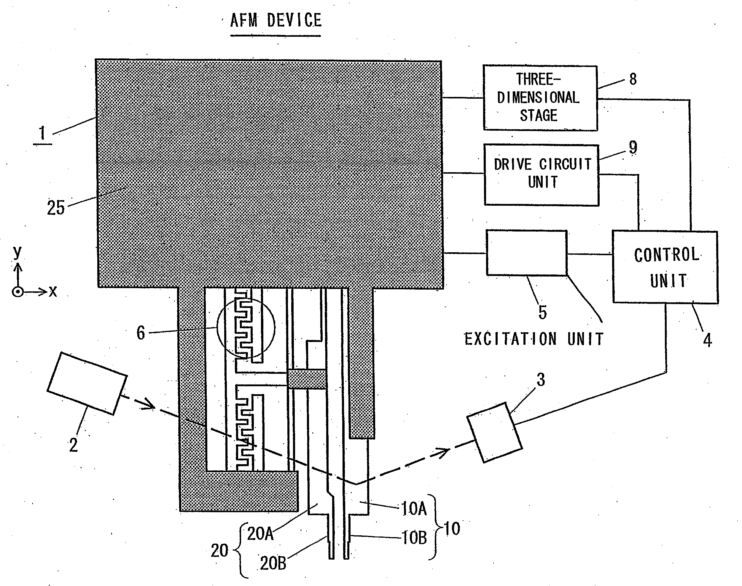
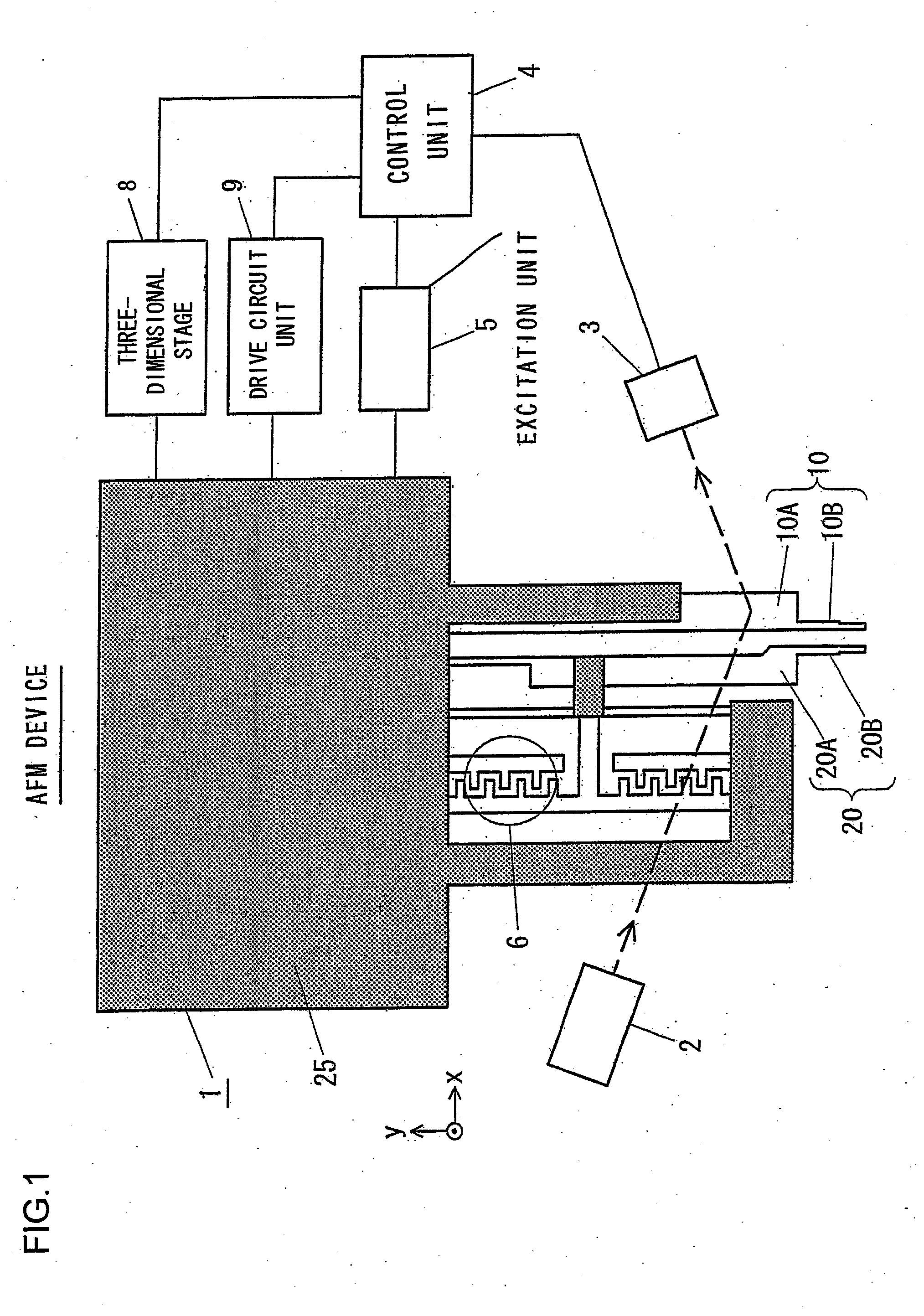
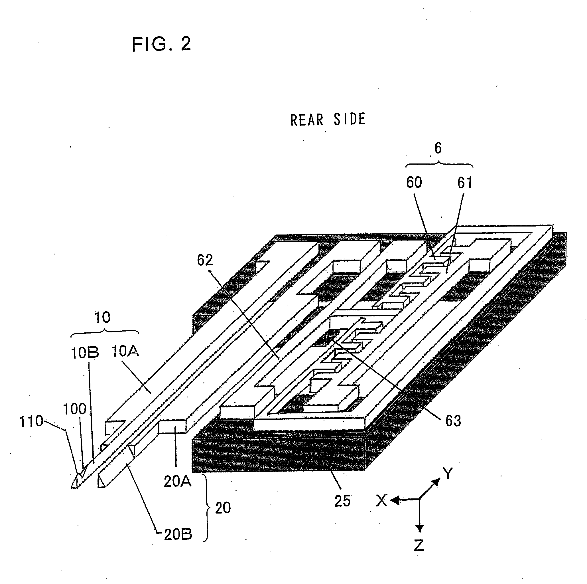
AFM tweezers includes: a first probe that comprises a triangular prism member having a ridge, a tip of which is usable as a probe tip in a scanning probe microscope; a second probe that comprises a triangular prism member provided so as to open / close with respect to the first probe. The first probe and the second probe are juxtaposed such that a predetermined peripheral surface of the triangular prism member of the first probe and a predetermined peripheral surface of the triangular prism member of the second probe face substantially in parallel to each other, and the first probe formed of a notch that prevents interference with a sample when the sample is scanned by the tip of the ridge.

Description

INCORPORATION BY REFERENCE[0001]The disclosure of the following priority application is herein incorporated by reference:[0002]Japanese Patent Application No. 2007-165641 filed Jun. 22, 2007.BACKGROUND OF THE INVENTION[0003]1. Field of the Invention[0004]The present invention relates to AFM (Atomic Force Microscope) tweezers with a probe that can be used as a probe tip for use in a scanning probe microscope, to a method for producing such AFM tweezers, and to a scanning probe microscope.[0005]2. Description of Related Art[0006]So-called AFM tweezers that include two probes between which a sample is to be inserted and grip / release the sample have been developed to be applied to manipulation of samples to be observed by a scanning probe microscope.[0007]Such AFM tweezers in a cantilever used in, for example, a scanning probe microscope include the following: (1) AFM tweezers including two carbon nanotubes attached to a probe tip attached to the tip of a cantilever made of silicon (see...

Claims


Application Information

Patent Timeline
IPC IPC(8): G12B21/08B25J7/00B25J15/08B81B3/00B81C1/00G01Q60/38G01Q80/00
CPCB82Y35/00Y10S977/962G01Q80/00G01Q60/38
Inventor KOBAYASHI, TATSUYASUZUKI, MASATOYASUTAKE, MASATOSHIUMEMOTO, TAKESHI
Owner AOI ELECTRONICS CO LTD
Learn More