
Reinforced double-walled pipe and manufacturing method

a double-walled pipe and manufacturing method technology, applied in the direction of pipes, pipe protection against damage/wear, mechanical equipment, etc., can solve the problems of clogging the pipe, reducing the useful internal diameter of the pipe, and affecting the service life of the pipe, so as to reduce the steel thickness, improve the service life, and improve the effect of mechanical resistan

Inactive Publication Date: 2009-01-01
INST FR DU PETROLE
View PDF6 Cites 41 Cited by
  • Summary
  • Abstract
  • Description
  • Claims
  • Application Information

AI Technical Summary

Benefits of technology

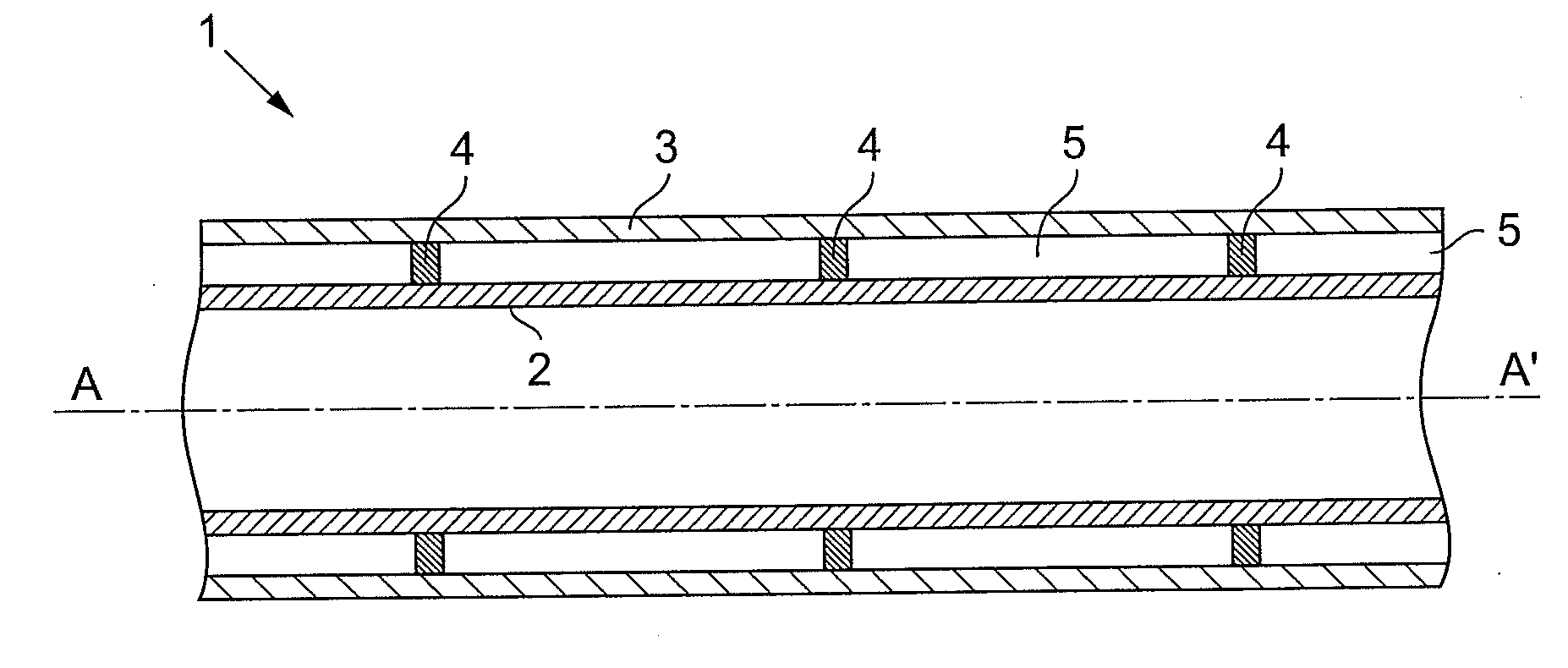
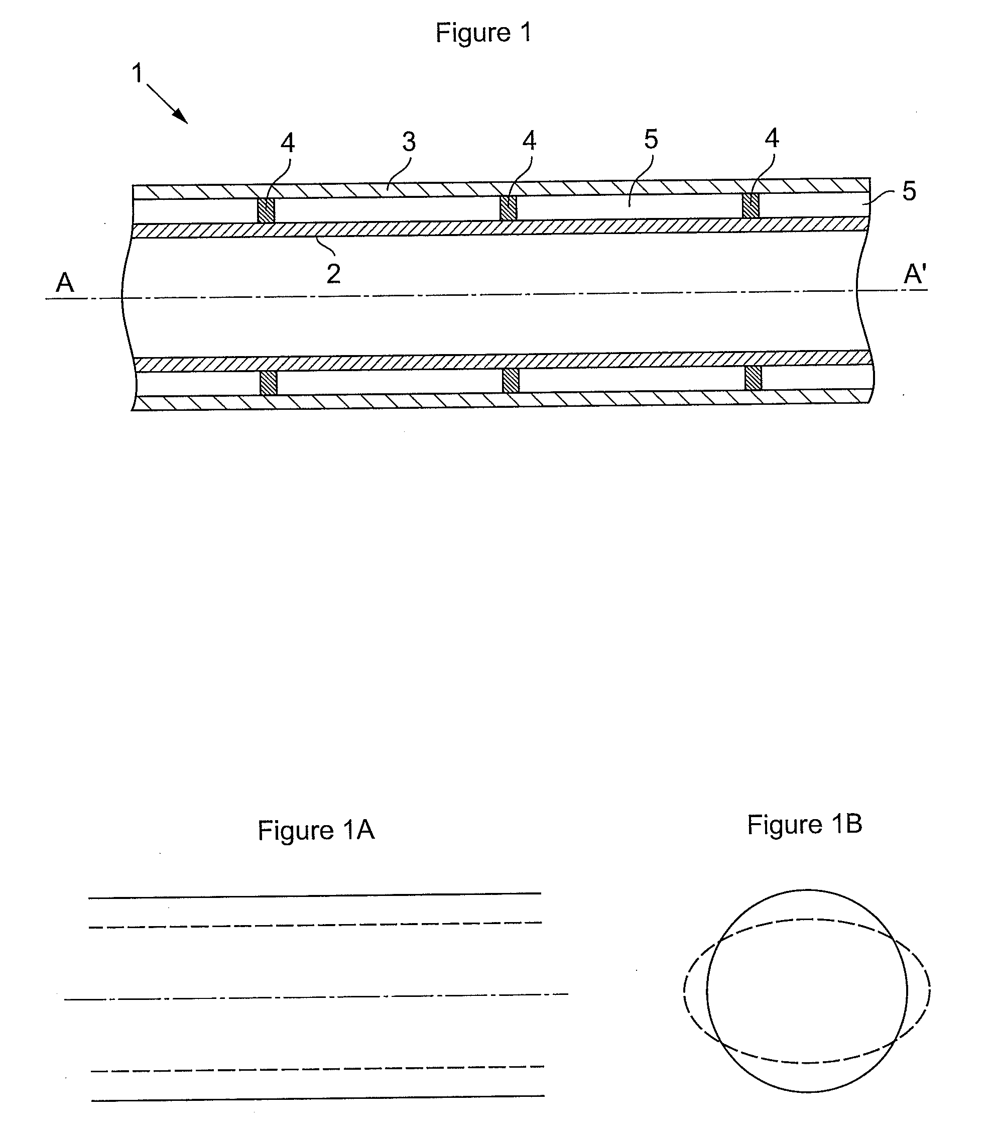
[0009]In general terms, the invention describes a reinforced double-walled pipe comprising a rigid internal tube arranged in a rigid external tube, the tubes being separated by an annular space, centering elements holding the internal tube in position in relation to the external tube. According to the invention, said external tube withstands alone an external pressure at least above 50 bars and the centering elements are in contact with the internal tube and the external tube so as to reinforce the mechanical resistance of the external tube to the external pressure.
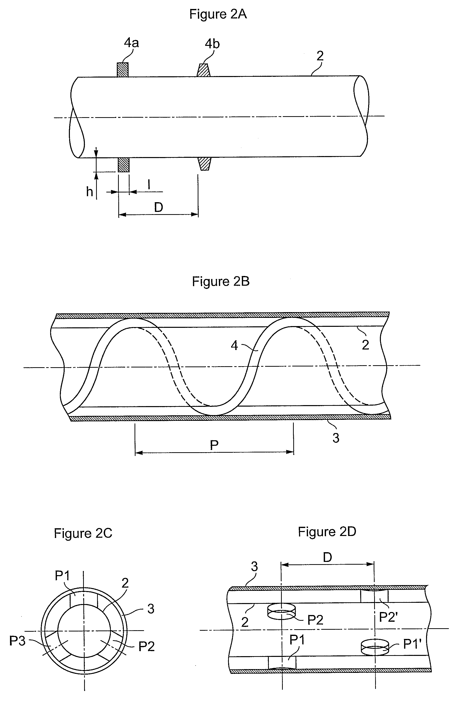
[0015]The invention also describes a method of manufacturing a reinforced double-walled pipe, said pipe comprising a rigid internal tube arranged in a rigid external tube, the tubes being separated by an annular space, centering elements holding the internal tube in position in relation to the external tube. According to the invention, the rigid external tube is selected in such a way that said external tube withstands an external pressure above 50 bars and the centering elements are placed in contact with the internal tube and the external tube so as to increase the mechanical resistance of the external tube to the external pressure.
[0020]The pipe according to the invention has a higher mechanical resistance allowing to reduce the steel thicknesses used and therefore to lighten the pipe. Thus, the pipe according to the invention can be used for the development of reservoirs located at great water depths.

Problems solved by technology

Too great cooling of these petroleum products would be problematic under normal production conditions and in the case of production stop.
Cooling of the transported petroleum effluent can in fact cause viscosity increase, paraffin precipitation and asphaltenes flocculation that increase the viscosity of the effluent and lead to deposits that reduce the useful internal diameter of the pipe, or to the formation of gas hydrates that may clog the pipe.
However, the use of pipe-in-pipe type lines is penalized by the own weight of these pipes.

Method used


Image

  • Reinforced double-walled pipe and manufacturing method
  • Reinforced double-walled pipe and manufacturing method
  • Reinforced double-walled pipe and manufacturing method

Examples


Embodiment Construction

[0027]Double-walled pipe 1 of longitudinal axis AA′, partially shown in FIG. 1, comprises an internal wall or tube 2 commonly referred to as flowline and an external wall or tube 3 commonly referred to as carrier pipe. Internal tube 2 wherein the fluid to be transported circulates provides internal pressure strength and sealing against the fluid transported, a petroleum effluent for example. External tube 3 provides external pressure strength and sealing against the medium external to pipe 1, the sea water for example.

[0028]In general, tubes 2 and 3 are made of a metallic material, steel, aluminium or titanium for example. The invention can also be implemented with tubes 2 and 3 made of a composite material with a matrix made of a thermoplastic or thermosetting organic material, reinforced with carbon, glass or other fibers.

[0029]Internal tube 2 is positioned in relation to external tube 3 by means of centering elements or radial stops 4 so as to be substantially coaxial. Centering ...


PUM

PropertyMeasurementUnit
pressureaaaaaaaaaa
Young's modulusaaaaaaaaaa
pressureaaaaaaaaaa

Abstract

The double-walled pipe comprises a rigid internal tube 2 arranged in a rigid external tube 3, the tubes being separated by an annular space, centering elements holding the internal tube in position in relation to the external tube.External tube 3 withstands alone an external pressure at least above 50 bars.The mechanical resistance of the pipe to the external pressure is reinforced by placing centering elements 4 in contact with internal tube 2 and with external tube 3.

Description

FIELD OF THE INVENTION[0001]The present invention relates to the field of double-walled pipes for fluid transportation.BACKGROUND OF THE INVENTION[0002]A double-walled pipe, commonly referred to as pipe-in-pipe, consists of two respectively internal and external coaxial metallic tubes, separated by an annular space filled with an insulating material. The internal tube is held in position in relation to the external tube by centering elements commonly referred to as spacers. Spacers generally have the shape of rings.[0003]Double-walled pipes are notably used in the petroleum industry for carrying oil from a wellhead at the sea bottom to a surface processing plant. The pipes installed at the sea bottom, commonly referred to as flowlines, mainly undergo static mechanical stresses; on the other hand, the pipes connecting the sea bottom to the surface, commonly referred to as risers, undergo static and dynamic mechanical stresses.[0004]Offshore reservoir development is performed up to wa...

Claims


Application Information

Patent Timeline
Patent Type & Authority Applications(United States)
IPC IPC(8): F16L9/18B23P15/26
CPCF16L9/042F16L9/047F16L9/18Y10T29/49361F16L59/065F16L59/14F16L57/02
Inventor AVERBUCH, DANIELMARTINEZ, MICKAEL
Owner INST FR DU PETROLE
Learn More