Method of Automatically controlling the Trajectory of a Drilled Well

a technology of automatic control and drilling well, which is applied in the direction of directional drilling, adaptive control, instruments, etc., can solve the problem of drilling bit veering o

Active Publication Date: 2009-01-01
SCHLUMBERGER TECH CORP
View PDF10 Cites 94 Cited by
  • Summary
  • Abstract
  • Description
  • Claims
  • Application Information

AI Technical Summary

Benefits of technology

[0011]In one aspect, a method of controlling the trajectory of a drill string includes providing a steering behavior model having a build rate equation and a turn rate equation, calibrating the steering behavior mode by minimizing any variance between an actual build rate and an actual turn rate of a bottom-hole assembly generated by a first set of tool settings and a first estimated build rate and a first estimated turn rate generated by inputting the first set of tool settings into the steering behavior model, determining an estimated position and an estimated azimuth and inclination data set of the bottom-hole assembly by inputting a second set of tool settings into the calibrated steering behavior model, comparing the estimated position and the estimated azimuth and inclination data set to a well plan to determine any deviation of the bottom-hole assembly therefrom, and determining a corrective action to correct the any deviation.
[0012]In another aspect, a method of controlling the trajectory of a drill string includes providing a steering behavior modal having a build rate equation and a turn rate equation, calibrating the steering behavior model at a first interval by minimising any variance between an actual build rate and an actual turn rate of a bottom-hole assembly generated by a first set of tool settings and a first estimated build rate and a first estimated turn rate generated by inputting the first set of tool settings into the steering behavior model, determining a second estimated build rate and a second estimated turn rate at a second interval by inputting a subsequent second set of tool settings into the calibrated steering behavior model, comparing the second estimated build rate and the second estimated turn rate to a well plan to determine any deviation of the bottom-hole assembly therefrom, and determining with a controller a corrective action to correct the any deviation.
[0013]In another aspect, a method of controlling the trajectory of a drill string includes providing a steering behavior model having a build rate equation and a turn rate equation of a bottom-hole assembly, providing an actual azimuth and inclination data set for a first interval drilled with a first set of tool settings, determining an actual build rate and an actual turn rate for the first interval from the actual azimuth and inclination data set, calibrating the steering behavior model by minimizing any variance between the actual build rate and the actual turn rate and a first estimated build rate and a first estimated turn rate generated by inputting the first set of tool settings into the steering behavior model, determining a second estimated build rate and a second estimated turn rate with the calibrated steering behavior model for a subsequent second interval dulled with a subsequent second set of tool settings, integrating the second estimated build rate and the second estimated turn rate over the second interval to produce a second estimated azimuth and inclination data set for the second interval, integrating the second estimated azimuth and inclination data set over the second interval to produce an estimated position of the bottom-hole assembly, comparing with a controller at least one of the second estimated build rate and the second estimated turn rata, the second estimated azimuth and inclination data set, and the estimated position to a well plan to determine a corrective action, and determining with the controller a set of recommended tool settings from the corrective action and an inverse application of the calibrated steering behavior model.

Problems solved by technology

Often the drill bit will veer off of a planned drilling trajectory because of an unpredicted nature of the formations being penetrated or the varying forces that the drill bit experiences.
As this decision making process is neither systematic nor predictable due to the lack of uniformity between wells, formations and BHAs used, directional drillers often differ in their decision making, yet these decisions generally all relate to maintaining the drilling assembly in accordance with a previously detailed well drilling plan.

Method used


Image

  • Method of Automatically controlling the Trajectory of a Drilled Well
  • Method of Automatically controlling the Trajectory of a Drilled Well
  • Method of Automatically controlling the Trajectory of a Drilled Well

Examples


Embodiment Construction

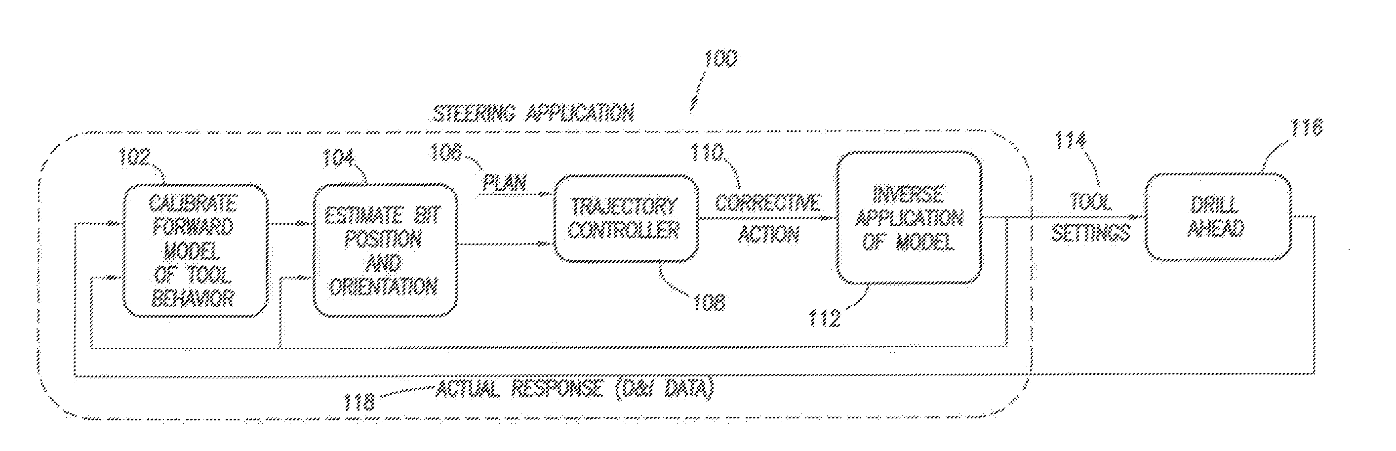
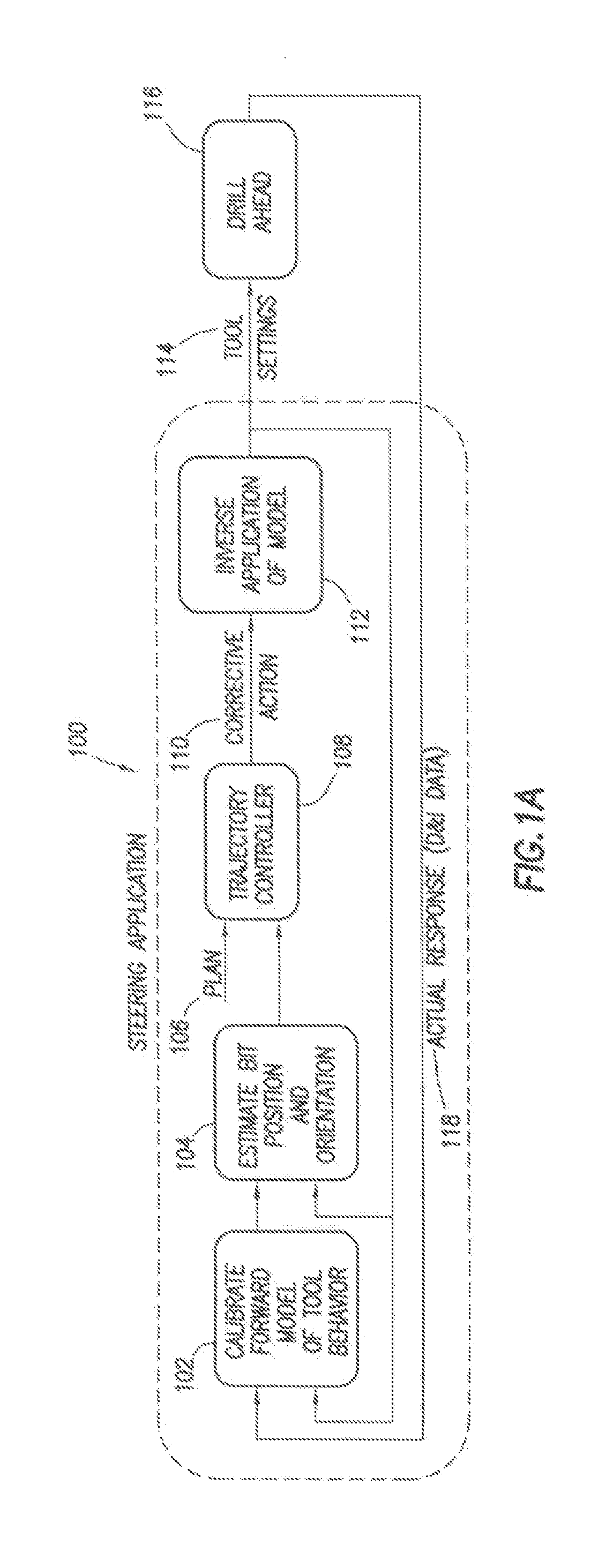
[0023]The current invention provides a system and method of automatically controlling the trajectory of a drilled well. To automatically control the trajectory of a drilled well, a steering behavior model, which can be mathematical, software, or other digital form, is provided. The steering behavior model can use any methodology or tool to simulate the steering behavior of a drill string, or more specifically a bottom-hole assembly. The present invention relates to the calibration of a steering behavior model to minimize a variance between the steering behavior model of the well and the actual drilled well. FIG. 1A illustrates an example flow diagram. The steering application 100 can be used to create an automatic trajectory controller and / or an automatic steering application 100. A controller can be a computer. A controller can be any electrical or mechanical device, for example, for determining any corrections necessary to align an actual trajectory with a well plan or any other r...


PUM


Abstract

Steering behavior model can include build rate and / or turn rate equations to modal bottom-hole assembly behavior. Build and / or turn rate equations can be calibrated by adjusting model parameters thereof to minimize any variance between actual response 118 and estimated response produced for an interval of the well. Estimated position and orientation 104 of a bottom-hole assembly along a subsequent interval can be generated by inputting subsequent tool settings into the calibrated steering behavior model. Estimated position and orientation 104 can be compared to a well plan 106 with a controller 108 which determines a corrective action 110. Corrective action 110 can be converted from a build and / or turn rate to a set of recommended tool settings 114 by using an inverse application 112 of the steering behavior model. As additional data 118 becomes available, steering behavior model can be further calibrated 102 through iteration.

Description

BACKGROUND[0001]The invention relates generally to methods of directionally drilling wells, particularly wells for the production of hydrocarbon products. More specifically, it relates to a method of automatic control of a steerable drilling tool to drill wells along a planned trajectory.[0002]When drilling oil and gas walls for the exploration and production of hydrocarbons it is often desirable or necessary to deviate a well in a particular direction. Directional drilling is the intentional deviation of the wellbore from the path it would naturally take. In other words, directional drilling is the steering of the drill string so that it travels in a desired direction.[0003]Directional drilling can be used for increasing the drainage of a particular well, for example, by forming deviated branch bores from a primary borehole. Directional drilling is also useful in the marine environment where a single offshore production platform can reach several hydrocarbon reservoirs by utilizing...

Claims


Application Information

Patent Timeline
Patent Type & Authority Applications(United States)
IPC IPC(8): E21B7/06
CPCE21B7/04E21B2200/20E21B44/00G05B13/04
Inventor PIROVOLOU, DIMITRIOS K.
Owner SCHLUMBERGER TECH CORP
Why Eureka
Try Eureka