Hydraulic control for a dual clutch transmission

a dual clutch transmission and hydraulic control technology, applied in the direction of mechanical actuated clutches, couplings, fluid couplings, etc., can solve the problems of transmission jams and inherently failsafe dual clutch transmissions

Inactive Publication Date: 2009-01-01
LUK LAMELLEN & KUPPLUNGSBAU BETEILIGUNGS KG
View PDF3 Cites 31 Cited by
  • Summary
  • Abstract
  • Description
  • Claims
  • Application Information

AI Technical Summary

Benefits of technology

[0005]This problem is solved by a dual clutch transmission comprising a first clutch, which is hydraulically actuated by a first hydraulic cylinder, and a second clutch, which is hydraulically actuated by a second hydraulic cylinder, in addition to several hydraulically actuated shift cylinders for shifting gears, which can be pressurized by means of a selector valve arrangement, wherein the first hydraulic cylinder and the second hydraulic cylinder and the selector valve arrangement are connected to the pressure side of a pressure device by means of safety valves, which are actuated in unison. Preferably provision is made for the safety valves to connect the first hydraulic cylinder and the second hydraulic cylinder and the selector valve arrangement to the pressure device in an operating position, and to separate the first hydraulic cylinder and the second hydraulic cylinder and the selector valve arrangement from the pressure device in an emergency position. Preferably provision is made for the first hydraulic cylinder and the second hydraulic cylinder to be depressurized in the emergency position. Furthermore, by preference provision is made for the shift cylinders to be depressurized in the emergency position. With such a valve system, it is possible by actuating a single valve, namely the safety valve, to convert the entire transmission including the dual clutch to a safe state, in which both clutches are disengaged and the shift state of the transmission is frozen. The safety valves are preferably combined in a safety valve block.
[0006]Preferably provision is made for each shift cylinder of a double piston to be connected to an output of a reversing valve, where the reversing valve includes a plurality of outputs and one output is connected to a first input of the reversing valve and the rest of the outputs are connected to a second input of the reversing valve in a hydraulically conductive connection, and where the shift cylinders of the double pistons that are not connected to an output of the reversing valve are connected to the second input of the reversing valve and the first and second inputs of the reversing valve can be pressurized alternately with the high or low pressure. The pistons of two shift cylinders at a time are preferably coupled together into a double piston, where one shift cylinder in each instance can be pressured with a high pressure and the other shift cylinders can be pressurized with a low pressure. The reversing valve is preferably a rotary valve. Preferably provision is made for the first input of the reversing valve to be connected to a first output of a shifting pressure regulating valve and for the second input of the reversing valve to be connected to a second output of the shifting pressure regulating valve, where the first and second outputs of the shifting pressure regulating valve can be connected alternately to an input of the shifting pressure regulating valve at which the high pressure is present and an input at which the low pressure is present. The pressure device is preferably a pressure accumulator, which is charged with a hydraulic fluid by a hydraulic pump. The high pressure is preferably approximately the pressure on the pressure side of the hydraulic pump and the low pressure approximately the pressure on the suction side of the hydraulic pump. This approximately means that these pressure values may be somewhat lower due to interposed elements which have for example a throttling effect. The pressure on the suction side of the pump here is preferably approximately the pressure in a tank for a hydraulic fluid, and thus approximately the ambient pressure.
[0007]This problem named at the beginning is also solved by a hydraulic system, in particular for actuating a dual clutch transmission comprising a first clutch, which is hydraulically actuated by a first hydraulic cylinder, and a second clutch, which is hydraulically actuated by a second hydraulic cylinder, in addition to several hydraulically actuated shift cylinders for shifting gears, which can be pressurized by means of a selector valve arrangement, wherein the first hydraulic cylinder and the second hydraulic cylinder and the selector valve arrangement are connected to the pressure side of a pressure device by means of safety valves, which are actuated in unison. Refinements of the hydraulic system have the features or combinations of features named in the subordinate claims for the dual clutch transmission according to the invention.

Problems solved by technology

Dual clutch transmissions of this sort are not inherently “fail-safe.” For example, if both gear train clutches are engaged simultaneously with a gear selected, the transmission jams.

Method used


Image

  • Hydraulic control for a dual clutch transmission
  • Hydraulic control for a dual clutch transmission

Examples


Embodiment Construction

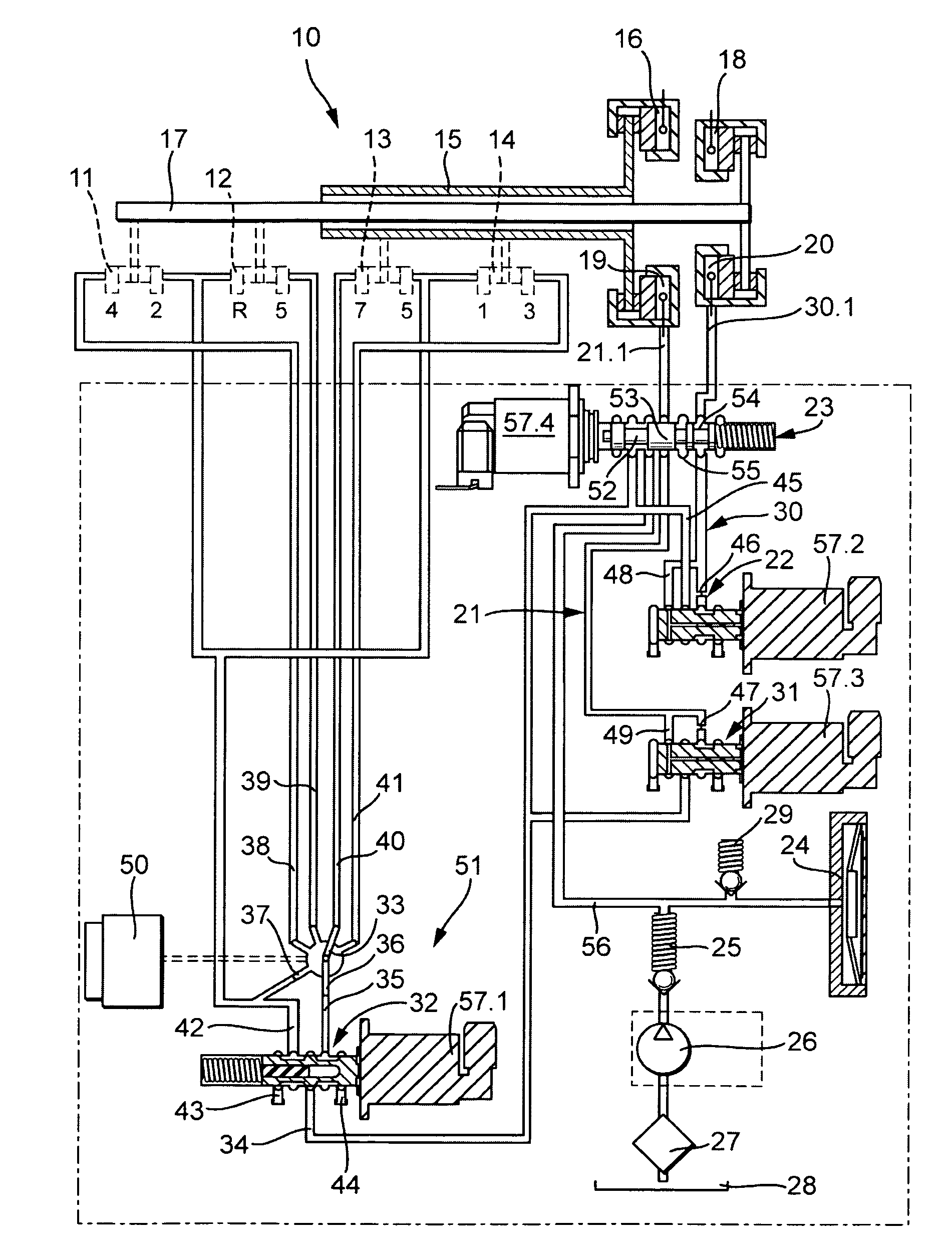
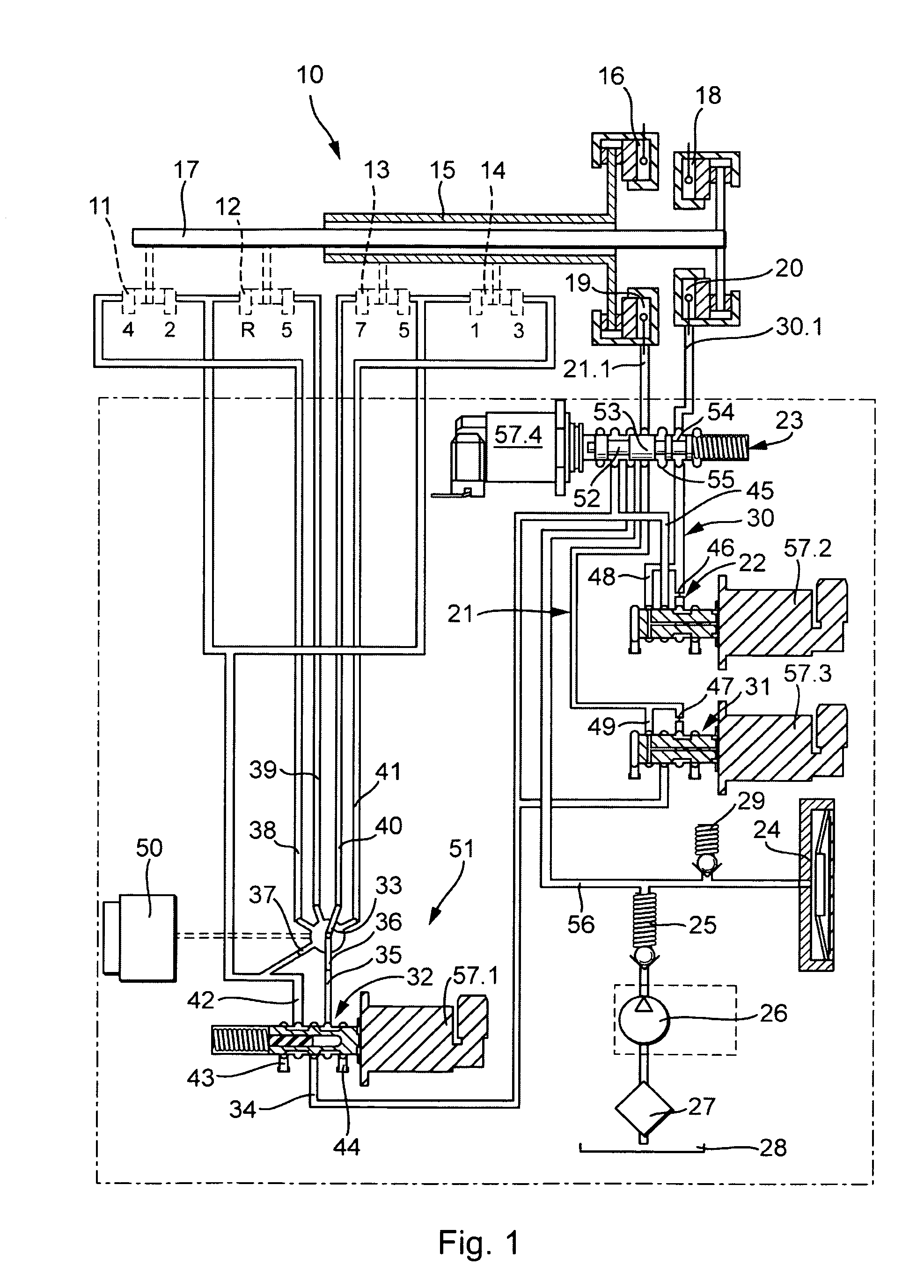
[0010]FIG. 1 shows an exemplary embodiment of dual clutch transmission 10 according to the invention, which is depicted only schematically here. In the present exemplary embodiment an 8-gear transmission is assumed, comprising seven forward gears and one reverse gear. The individual gears are shifted by shift cylinders 11, 12, 13 and 14. In the exemplary embodiment, shift cylinder 11 shifts gears two and four, shift cylinder 12 shifts the reverse gear and gear six, shift cylinder 13 gears five and seven and shift cylinder 14 gears one and three. The shift cylinders are hydraulically actuated and have two end positions, each of which corresponds to one of the two gears, as well as a middle position in which neither of the two gears is selected. FIG. 1 indicates schematically that gears one, three, five and seven, i.e., all of the odd numbered gears, interact with first transmission input shaft 15, which may be engaged with or disengaged from the crankshaft of a combustion engine (not...


PUM


Abstract

A dual clutch transmission comprising a first clutch (16), which is hydraulically actuated by a first hydraulic cylinder (19), and a second clutch (18), which is hydraulically actuated by a second hydraulic cylinder (20), in addition to a plurality of hydraulically actuated shift cylinders (11, 12, 13, 14) for shifting gears, which can be subjected to pressure (p1, p2) by means of a selector valve arrangement (51), wherein the first hydraulic cylinder (19) and the second hydraulic cylinder (20) and the selector valve arrangement (51) are connected to a pressure side of a pressure device (24, 25, 26, 27, 28) by means of safety valves (52, 53, 54), which are actuated in unison.

Description

CROSS-REFERENCE TO RELATED APPLICATIONS[0001]This application is filed under 35 U.S.C. §120 and §365(c) as a continuation of International Patent Application PCT / DE2007 / 000253, filed Feb. 12, 2007, which application is incorporated herein by reference. This application also claims priority from German Patent Application No. 10 2006 010 631.8, filed Mar. 8, 2006, which application is incorporated herein by reference.FIELD OF THE INVENTION[0002]The present invention relates to a dual clutch transmission as well as a hydraulic system for actuating a dual clutch transmission.BACKGROUND[0003]It is known to shift gear-changing transmissions, in particular dual clutch transmissions, hydraulically, as well as to actuate the two clutches hydraulically.[0004]Dual clutch transmissions of this sort are not inherently “fail-safe.” For example, if both gear train clutches are engaged simultaneously with a gear selected, the transmission jams. In the event of an error, it is therefore necessary to...

Claims


Application Information

Patent Timeline
Patent Type & Authority Applications(United States)
IPC IPC(8): F16D21/00F16D31/00F16H61/12
CPCF16D48/0206F16D2048/0221F16H2061/1232F16H61/688F16H61/12
Inventor STAUDINGER, MARTINMUELLER, ERICDREHER, FELIX
Owner LUK LAMELLEN & KUPPLUNGSBAU BETEILIGUNGS KG
Why Eureka
Try Eureka