Energy Efficient House Ventilation

a house ventilation and energy saving technology, applied in the field of comfort systems for houses, can solve the problems of corrosion failure, ventilation of most homes, and comfort problems, and achieve the effect of reducing the degree of mechanical ventilation

Inactive Publication Date: 2009-01-01
CARRIER CORP
View PDF18 Cites 57 Cited by
  • Summary
  • Abstract
  • Description
  • Claims
  • Application Information

AI Technical Summary

Benefits of technology

[0008]Briefly, in accordance with one aspect of the invention, the degree of mechanical ventilation is reduced to compensate for an increase in the natural ventilation that occurs from the “stack effect”. In this manner, over ventilation during periods of hot or cold weather is minimized.

Problems solved by technology

The fact is that many homes are actually leakier than 0.15 air changes per hour, so that the prescribed ventilation air flow by ASHRAE will result in over ventilation of most homes.
Though conservative, from a ventilation standpoint, too much ventilation air, particularly during periods of cold weather, can cause comfort problems for the occupants due to cold blow, durability problems for the HVAC equipment (too cold a return air temperature to the furnace causes condensation on the heat exchanger and vent surfaces that leads to corrosion failure), and unnecessary energy consumption to treat the cold outside air.
Though very low in cost to apply, such a system provides little control over the amount of outside air being pulled into the return duct.
Uncontrolled outside air will cause cold blow and lead to furnace heat exchanger and vent corrosion, particularly during cold weather.
Though this ensures that some control is maintained over the amount of ventilation airflow, there is no means in which to prevent over ventilation during periods of cold weather, nor to avoid the potential of cold blow and furnace heat exchanger and vent corrosion.
However, unlike the above mentioned apparatus, this is not an intelligent control and it is therefore not very precise, such that the amount of ventilation air ingested is highly variable.

Method used


Image

  • Energy Efficient House Ventilation
  • Energy Efficient House Ventilation
  • Energy Efficient House Ventilation

Examples


Embodiment Construction

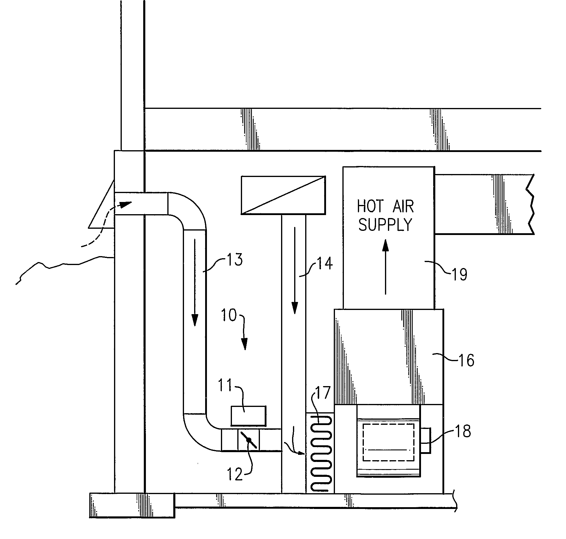
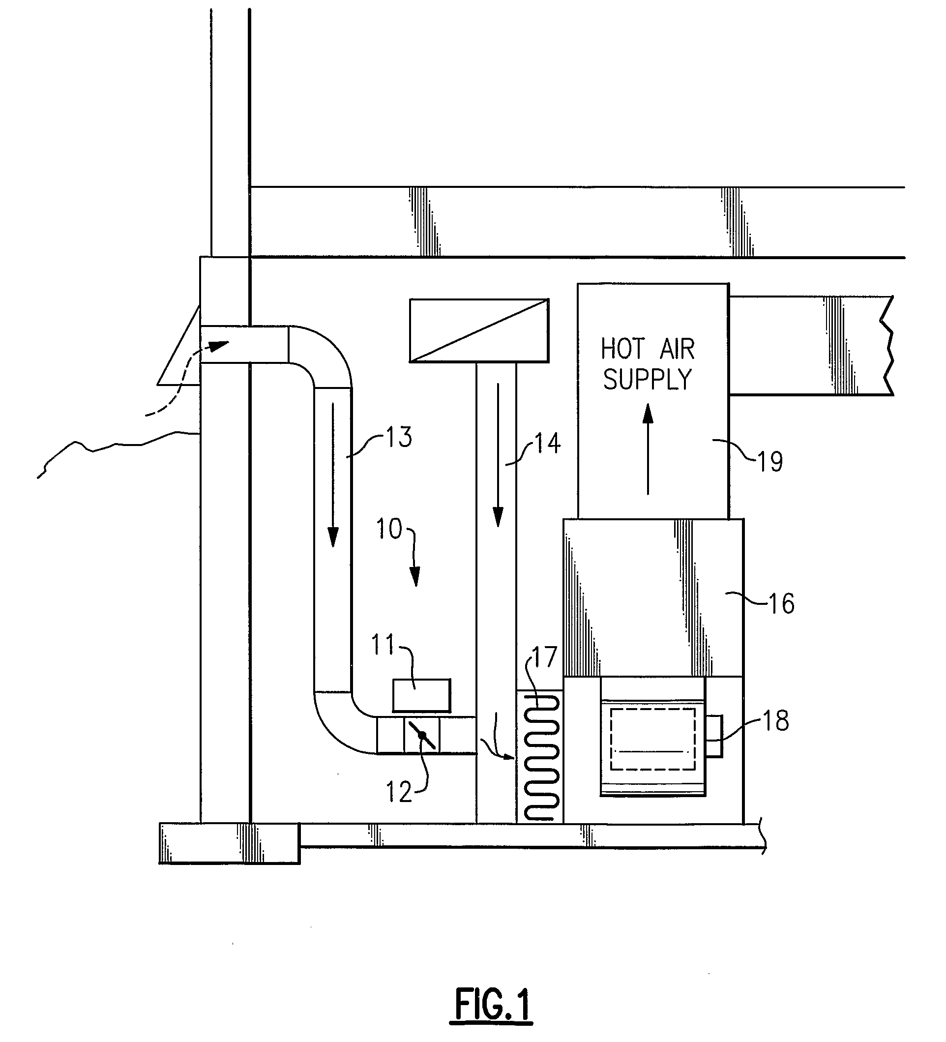
[0023]Referring now to FIG. 1, the invention is shown generally at 10 as applied to a damper control 11 which is operative to control the position of a damper 12 in a manner to be described more fully hereinafter.

[0024]The damper 12 is disposed within an outside air duct 13 for regulating the amount of outside air that passes through the outside air duct 13 to a return air duct 14. The return air duct 14 is installed in such a manner that it conducts the flow of relatively cool air from the space being heated back to a furnace 16 by way of an air filter 17. A blower 18 in the furnace 16 acts to draw into the furnace the return air from the return air duct 14, as well as outside air through the outside air duct 13 when the damper 12 is open. The air mixture is then heated by the furnace 16 and delivered to the spaced to be heated by way of the hot air duct 19.

[0025]It should be mentioned that the purpose of introducing the outside air into the system is to ensure that the quality of ...


PUM


Abstract

A method and apparatus for maintaining an acceptable level of outside air exchange rate in a structure. The natural ventilation rate is determined as a function of the outdoor air temperature, and the amount of mechanically induced ventilation that is used to supplement the natural air ventilation is controlled such that the sum of the natural occurring ventilation and the mechanically induced ventilation is maintained by a substantially constant predetermined level. One approach is to use a stepper motor to modulate the position of the damper, while another approach is to use an on / off motor damper and to close the damper at outdoor temperatures below a threshold level and to otherwise leave the damper open and use the regular on / off cycle of the system blower to control the flow of outdoor air, with provision for allowing the fan to remain on for a calculated period of time after the system is cycled off to thereby maintain the desired level of ventilation. Can also vary the speed of the furnace blower or a separate ventilation fan motor.

Description

BACKGROUND OF THE INVENTION[0001]This invention relates generally to comfort systems for houses and, more particularly to a method and apparatus for regulating the flow of outside air into a home to maintain the air quality therein.[0002]The ASHRAE standard for acceptable ventilation and air quality in low rise residential buildings prescribes a fixed amount of outside ventilation air that must be provided to the home on a continuous, 24 hour per day, basis. In formulating the standard, they presumed that every house has an equivalent of a 0.15 air change rate per hour, and then requires mechanical ventilation air flow to achieve at least 0.35 air changes per hour, which is the level deemed “healthy” by most indoor air quality experts. The degree of mechanical ventilation air flow required is then a simple function of the size of the home and does not consider actual home infiltration rates.[0003]The fact is that many homes are actually leakier than 0.15 air changes per hour, so tha...

Claims


Application Information

Patent Timeline
Patent Type & Authority Applications(United States)
IPC IPC(8): F24F7/00G05D23/32F24F7/007G05D7/00
CPCF24F11/0001F24F2007/004F24F2011/0002
Inventor DEMPSEY, DANIEL J.
Owner CARRIER CORP
Why Eureka
Try Eureka