Two-phase synchronous electric motor with permanent magnets for mechanical priming washing pumps of dishwashers and similar washing machines

a technology of synchronous electric motors and washing machines, which is applied in the direction of magnetic circuits, dynamo-electric machines, electrical apparatus, etc., can solve the problems of high loss, physical limitations of the currently available smc material, and the known drawbacks of electric motors of the type being considered

Active Publication Date: 2009-01-01
ASKOLL HLDG SRL
View PDF7 Cites 16 Cited by
  • Summary
  • Abstract
  • Description
  • Claims
  • Application Information

AI Technical Summary

Benefits of technology

[0015]This problem is solved, according to the present invention, by a two-phase synchronous electric motor, comprising a permanent-magnet rotor, rotating around a corresponding rotation axis, and a core lamination-pack stator, wherein a first and second pairs of pole pieces define a housing rotation seat for said rotor and wherein each pole piece comprises a core, having an end associated to said core lamination pack and a free end portion, facing, said rotor housing/rotation seat, a coil wound

Problems solved by technology

Although advantageous under many points of view, electric motors of the type being considered suffer from known and not yet overcome technical drawbacks, mainly constituted by an even very high demagnetization effect, accompanied by as high losses due to the Joule effect and high pick-up voltages.
But this solution has demagnetization problems due to a flow concentration in the core central area preventing a flow extension on the whole height of the pole piece end.
This is due to physical limitations of the currently available SMC material.
But in this way the length of the average turn, the coil resistive value increases, and higher losses due to the Joule effect as well as higher costs consequently occur.
More particularly, the problems are due to the fact that the SMC material is anisotropic and the permeability t

Method used


Image

  • Two-phase synchronous electric motor with permanent magnets for mechanical priming washing pumps of dishwashers and similar washing machines
  • Two-phase synchronous electric motor with permanent magnets for mechanical priming washing pumps of dishwashers and similar washing machines
  • Two-phase synchronous electric motor with permanent magnets for mechanical priming washing pumps of dishwashers and similar washing machines

Examples


second embodiment

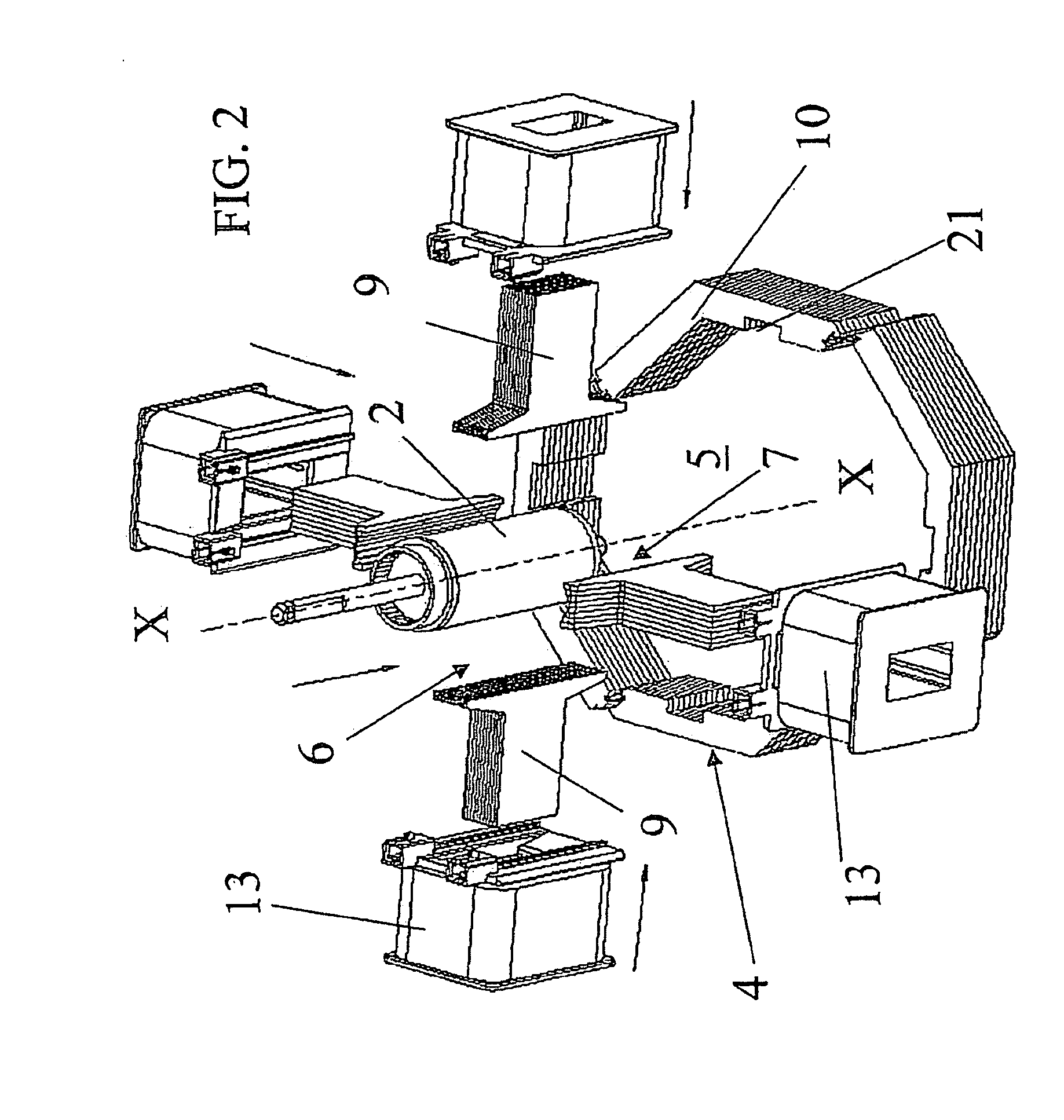
[0061]For example FIG. 6 shows a second embodiment wherein core laminations 15′ have the same size and the end 11 turned towards the rotor is, thus, flat and not concave as in the previous embodiment.

[0062]A skilled in the art could also assume to use the two solutions in a mixed way by using for example the concave surface solution only for one pair 6 of pole pieces and the flat surface for the other pair 7 of pole pieces.

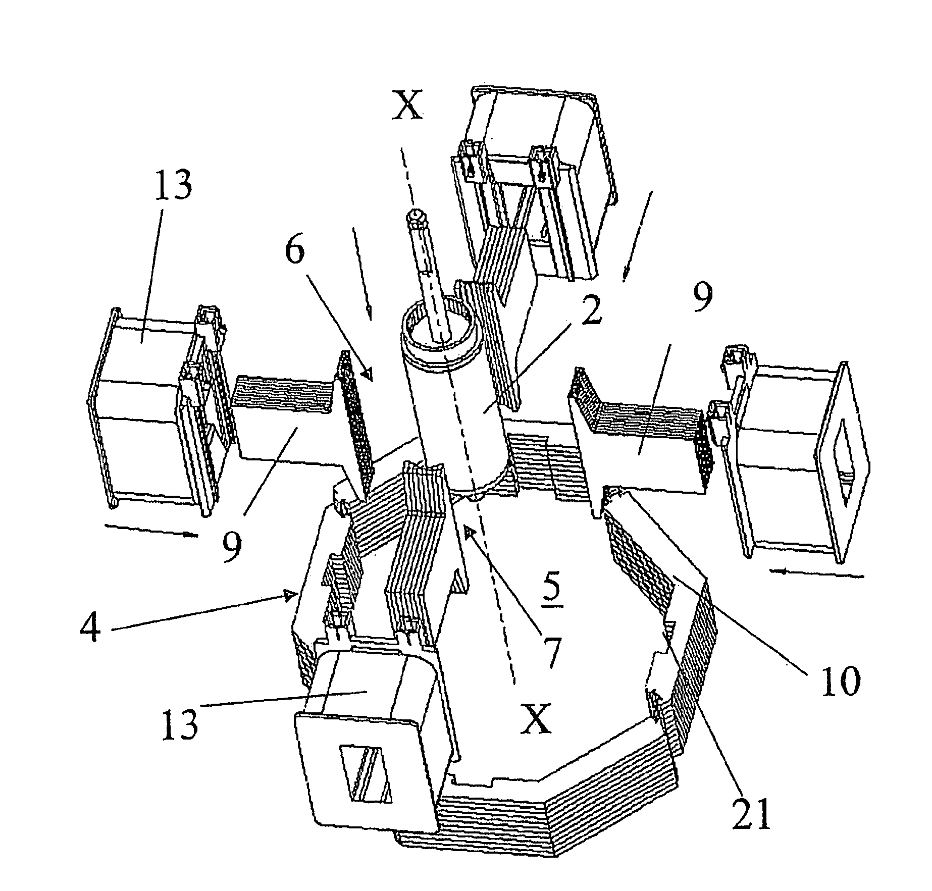
[0063]It must also be noted that the core 9 of each pole piece 8 is removably associated by pin-coupling or fitting to the core lamination pack 10 of the stator 4, as shown for example in FIGS. 4 and 5.

first embodiment

[0064]In this embodiment shown in FIGS. 4 and 5 the stator pack 10 and pole piece configuration is similar to the first embodiment with the end 11 of the pole pieces 8 having a flat shape and the end 14 of the core 9 being inserted in an indent 21 centrally cut in a section of the stator pack 10.

[0065]An elastic pin 25 is wedgedly inserted between the end 14 of the core 9 and the indent 21 seat.

[0066]In this way a quite high connection safety is obtained, with a lower assembly difficulty level.

[0067]Instead in the embodiment of FIG. 6 another system has been provided, for coupling the pole piece cores 9′ and the corresponding core lamination sections 10′ of the stator 4 pack.

[0068]The ends 24 of the cores 9′ turned towards the stator core lamination pack 10′ are substantially square-bracket-shaped so as to partially overlap the stator pack.

[0069]More in detail, these ends provide a central flat section 17 and opposed appendices 18, 19 perpendicularly extending with respect to the fl...


PUM


Abstract

The present invention relates to a two-phase synchronous electric motor (1), comprising a permanent-magnet rotor (2), rotating around a respective rotation axis (X), and a core lamination-pack (10) stator (4), wherein a first (6) and second (7) pairs of pole pieces (8) define a housing/rotation seat (5) for said rotor (2) and wherein each pole piece (8) comprises a core (9), having an end associated to the core lamination pack (10) and a free end portion (11), facing the rotor (2) housing/rotation seat (5), a coil (12) on a respective support (13) wedged on said core (9). Advantageously, at least the free end portion (11) of the core (9) of each pole piece (8) comprises a core lamination pack (15) extending in respective parallel planes to the rotation axis (X) of the permanent-magnet rotor (2). Advantageously, the core laminations (15) have a variable length to form a surface of said free end portion (11) of the core (9) of each pole piece (8) being concave in the axial direction and partially wrapping the rotor (2).
The particular structure of the stator (4) can be advantageously matched to the double-joint kinematic coupling between the rotor (2) and the load (31) and to the phase displacement capacitor C expedient between the windings associated to one of the pole piece pairs.

Description

FIELD OF APPLICATION[0001]The present invention relates to a two-phase synchronous electric motor with permanent magnets for mechanical priming washing pumps of dishwashers and similar washing machines.[0002]More particularly this invention relates to a two-phase electric motor comprising a permanent-magnet rotor and a core lamination-pack stator, wherein a first and second pairs of pole pieces define a housing / rotation seat for said rotor.[0003]Even more particularly, the present invention relates to a core lamination-pack stator, for a two-phase synchronous electric motor of the above type, wherein each pole piece comprises a core, with an end being associated to said core lamination pack and an opposite free end portion facing said rotor housing / rotation seat, and a coil for a stator winding on a corresponding support being wedged on said core.PRIOR ART[0004]It is well known how, to start centrifugal washing pumps, used in household washing machines (mainly dishwashers and the li...

Claims


Application Information

Patent Timeline
IPC IPC(8): H02K19/04
CPCH02K1/148H02K7/118H02K17/30H02K11/0073H02K17/08H02K7/14H02K11/33A47L15/42
Inventor MARIONI, ELIO
Owner ASKOLL HLDG SRL
Why Eureka
Try Eureka