Ultrasound transducer manufactured by using micromachining process, its device, endoscopic ultrasound diagnosis system thereof, and method for controlling the same

Active Publication Date: 2009-01-01
OLYMPUS CORP
View PDF9 Cites 80 Cited by
  • Summary
  • Abstract
  • Description
  • Claims
  • Application Information

AI Technical Summary

Benefits of technology

[0055]a conversion unit boosting an alternating current low voltage signal convey

Problems solved by technology

Because the conventional MUTs have been configured to have membranes of respective transducer cells that are continuous along the plane direction, the continuous configuration has interfered with the deformation of the membranes of the respective transducer

Method used


Image

  • Ultrasound transducer manufactured by using micromachining process, its device, endoscopic ultrasound diagnosis system thereof, and method for controlling the same
  • Ultrasound transducer manufactured by using micromachining process, its device, endoscopic ultrasound diagnosis system thereof, and method for controlling the same
  • Ultrasound transducer manufactured by using micromachining process, its device, endoscopic ultrasound diagnosis system thereof, and method for controlling the same

Examples


first embodiment

[0087]In the present embodiment, in an ultrasound transducer that is manufactured by using the micromachining process, a MUT for transmitting ultrasound by using the electrostatic force caused between the electrodes and the piezoelectric effect by the force activated in the piezoelectric film will be explained.

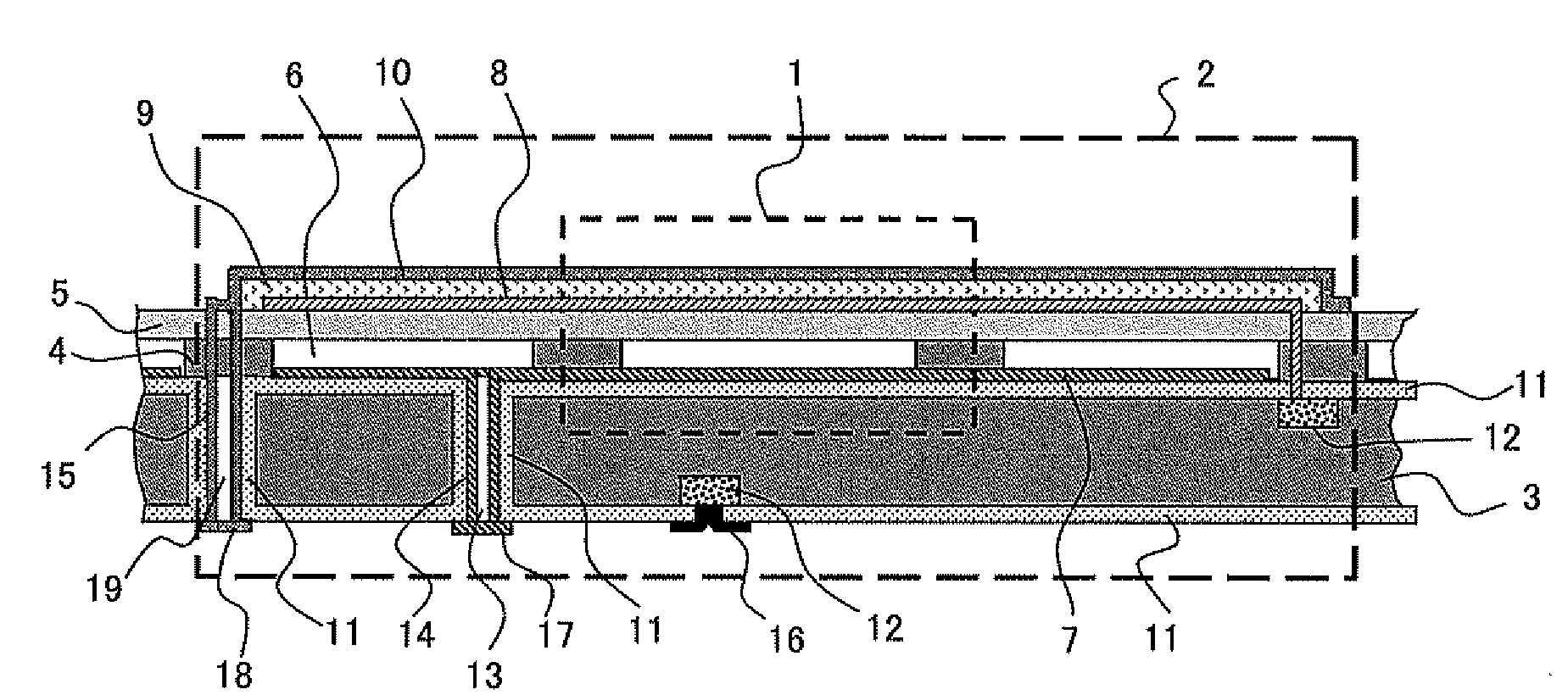
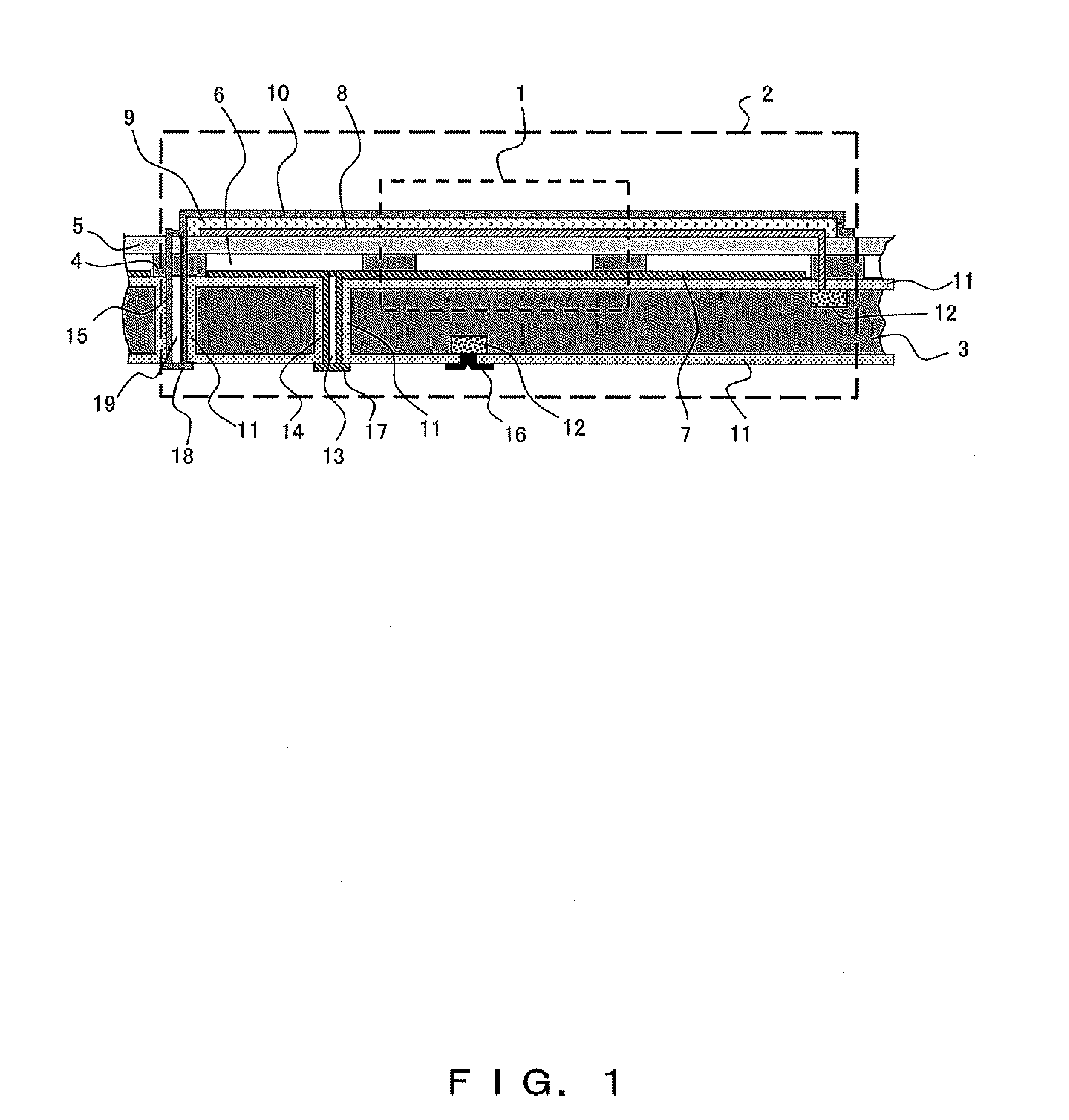
[0088]FIG. 1 is a cross-sectional view of a MUT element according to the present embodiment. The MUT element shown in FIG. 1 is a transducer that is the minimum unit to be controlled with the same phase and the same driving voltage, and is a micromachined ultrasound transducer consisting of a plurality of MUT cells 1.

[0089]A MUT element 2 includes a semiconductor substrate 3, supporting members 4, a membrane 5, cavities 6, a bottom electrode 7, a common ground electrode 8, a piezoelectric film 9, an upper electrode 10, an insulation film 11, a diffusion layer 12, through holes 13 and 19, a through hole wire 14 which is formed on the side wall of the through hole 13 and is elec...

second embodiment

[0132]In the present embodiment, a MUT that is obtained by adding, to the MUT according to the first embodiment, means for reducing a vibration loss will be explained. Also, in the explanation below, the same constituent elements as in the above embodiment are denoted by the same numerals; accordingly, for the detailed explanation thereof, to be referred to the above embodiment.

[0133]FIG. 5 shows a cross section of a MUT according to the present embodiment. The MUT shown in FIG. 5 is an ultrasound transducer that is manufactured by using the micromachining process. In the MUT shown in FIG. 5, the membranes between the cells are divided. The spaces between the adjacent cells are referred to as interstices 60.

[0134]Further, a bridge wire 65 between upper electrodes 10 of adjacent cells is provided on a bottom 61 of each interstice 60 so that the upper electrodes 10 of the adjacent cells are electrically continuous to each other through a via wire 64. Also, the respective bottom electr...

third embodiment

[0144]In the present embodiment, a MUT having a filtering function by which high-frequency components can be removed is explained. In the explanations below, the same constituent elements as in the above explanations are denoted by the same numerals; accordingly, refer to the above explanations for the detailed explanation thereof.

[0145]FIG. 6 shows a circuit configuration of the ultrasound probe 24 according to the present embodiment. FIG. 6 is obtained by adding a capacitor 70 to the circuit shown FIG. 3. One of the terminals of the capacitor 70 is connected to the transmission line 37, and the other terminal is grounded. By the capacitor 70, high-frequency components of the feedback signal S5 can be removed.

[0146]The high-frequency components to be removed are the high frequency waves corresponding to the high-order vibration mode. This type of high frequency wave can be removed by adjusting the capacitance of the capacitor 70. As a result of the removal of the high-frequency wav...


PUM


Abstract

An ultrasound transducer manufactured by using a micromachining process comprises: a first electrode into which a control signal for transmitting ultrasound is input; a substrate on which the first electrode is formed; a second electrode that is a ground electrode facing the first electrode with a prescribed space between the first and second electrodes; a membrane on which the second electrode is formed and which vibrates and generates the ultrasound when a voltage is applied between the first and second electrodes; a piezoelectric film contacting the membrane; and a third electrode electrically continuous to the piezoelectric film.

Description

CROSS REFERENCE TO RELATED APPLICATIONS[0001]This is a Continuation Application of PCT Application No. PCT / JP2007 / 052097, filed Feb. 7, 2007, which was not published under PCT Article 21 (2) in English.[0002]This application is based upon and claims the benefit of priority from the prior Japanese Patent Application No. 2006-057122, filed Mar. 3, 2006, the entire contents of which are incorporated herein by reference.BACKGROUND OF THE INVENTION[0003]1. Field of the Invention[0004]The present invention relates to a MUT (Micromachined Ultrasound Transducer).[0005]2. Description of the Related Art[0006]An ultrasound diagnosis method is commonly employed in which ultrasound is transmitted to walls of a body cavity and the state of the body cavity is converted into images on the basis of the echo signals thereof for the purpose of making diagnoses. An ultrasound endoscope is one of the devices used for this ultrasound diagnosis method.[0007]The ultrasound endoscope has an ultrasound probe...

Claims


Application Information

Patent Timeline
IPC IPC(8): H02N2/00A61B8/14
CPCA61B8/12A61B8/4483A61B8/445B06B1/0622B06B1/0292
Inventor ADACHI, HIDEOWAKABAYASHI, KATSUHIROMIZUNUMA, AKIKOSAWADA, YUKIHIKOIMAHASHI, TAKUYAFUJIMURA, TAKANAODOH, KI
Owner OLYMPUS CORP
Why Eureka
Try Eureka