Refrigeration unit

a refrigeration unit and compressor technology, applied in the field of refrigeration units, can solve the problems of affecting the performance of compressors, prone to perform the above protective operation of refrigeration units, and increasing thermal load rapidly, so as to prevent excessive increase of refrigerant pressure, reduce compressor performance, and reduce the effect of compressor performan

Inactive Publication Date: 2009-01-01
HOSHIZAKI ELECTRIC CO LTD
View PDF8 Cites 35 Cited by
  • Summary
  • Abstract
  • Description
  • Claims
  • Application Information

AI Technical Summary

Benefits of technology

[0018]According to the present invention, the refrigerant pressure gradually decreases while the performance of the compressor is gradually lowered, and if the pressure should fall to below the second predetermined pressure in a relatively short time, a normal state is restored. During this time, the refrigeration unit continues to fulfill its original function, because the compressor is not completely halted but its performance is gradually lowered until the refrigerant pressure falls to below the second predetermined pressure. Thus the temperature rise inside the refrigerator is prevented, and thereby the food or the like can be safely stored.
[0019]In most cases, according to the above control, the excessive increase of the refrigerant pressure due to a thermal overload is prevented or reduced, and thereby the compressor is prevented from halting. However, in case of an abnormal state such as a failure of a cooling fan, the refrigerant pressure continues to increase, even if the performance of the compressor is lowered when the refrigerant pressure exceeds the second predetermined pressure.
[0020]In this case, according to the present invention, the compressor is halted or limited to a safety operation rate (i.e., the protective operation is performed), when the refrigerant pressure exceeds the first predetermined pressure. Thus the refrigeration unit according to the present invention ensures protection thereof maintaining its original function when the refrigerant pressure increases due to a thermal overload.

Problems solved by technology

Generally, in the refrigeration unit of this type, the devices on the refrigerant circuit may be damaged, if the pressure in the refrigerant circuit increases in large excess.
However, a problem arises that a refrigeration unit is prone to perform the above protective operation at short intervals when it is used in a harsh environment (e.g., for industrial use).
In an industrial refrigerator installed in the kitchen of a restaurant, for example, its doors are frequently opened at lunch or dinner time and thereby the thermal load rapidly increases.
In these circumstances, the condenser is prone to degrade in its heat discharge.
Then the temperature inside the refrigerator rises, and food or the like inside the refrigerator may lowers in quality.
However, such parts are highly expensive and further it costs a great deal to do a test for proving design changes in this case.

Method used


Image

  • Refrigeration unit
  • Refrigeration unit
  • Refrigeration unit

Examples


first embodiment

[0031]A first embodiment of the present invention will be explained with reference to FIGS. 1 through 6, in which the present invention is applied to an industrial refrigerator-freezer.

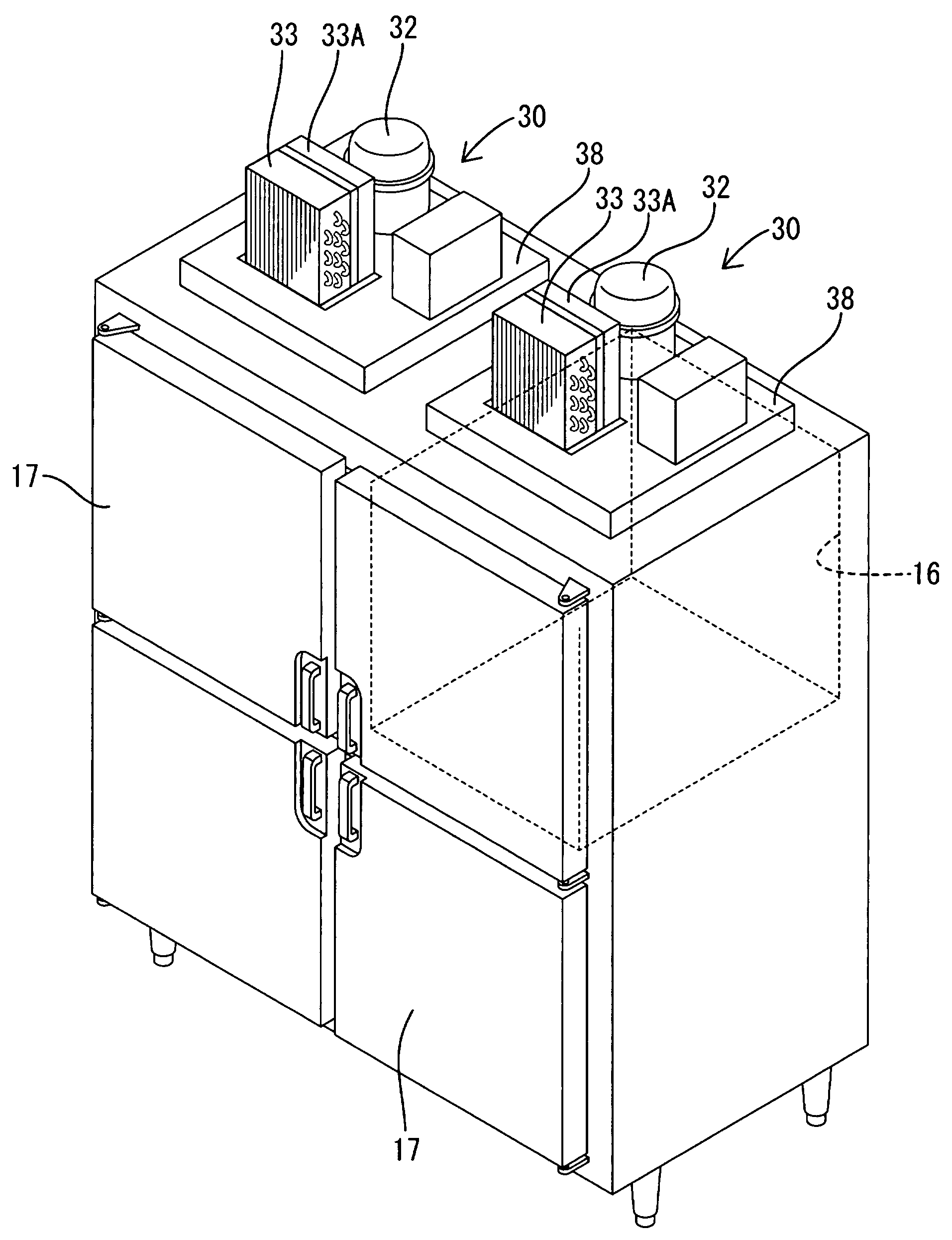
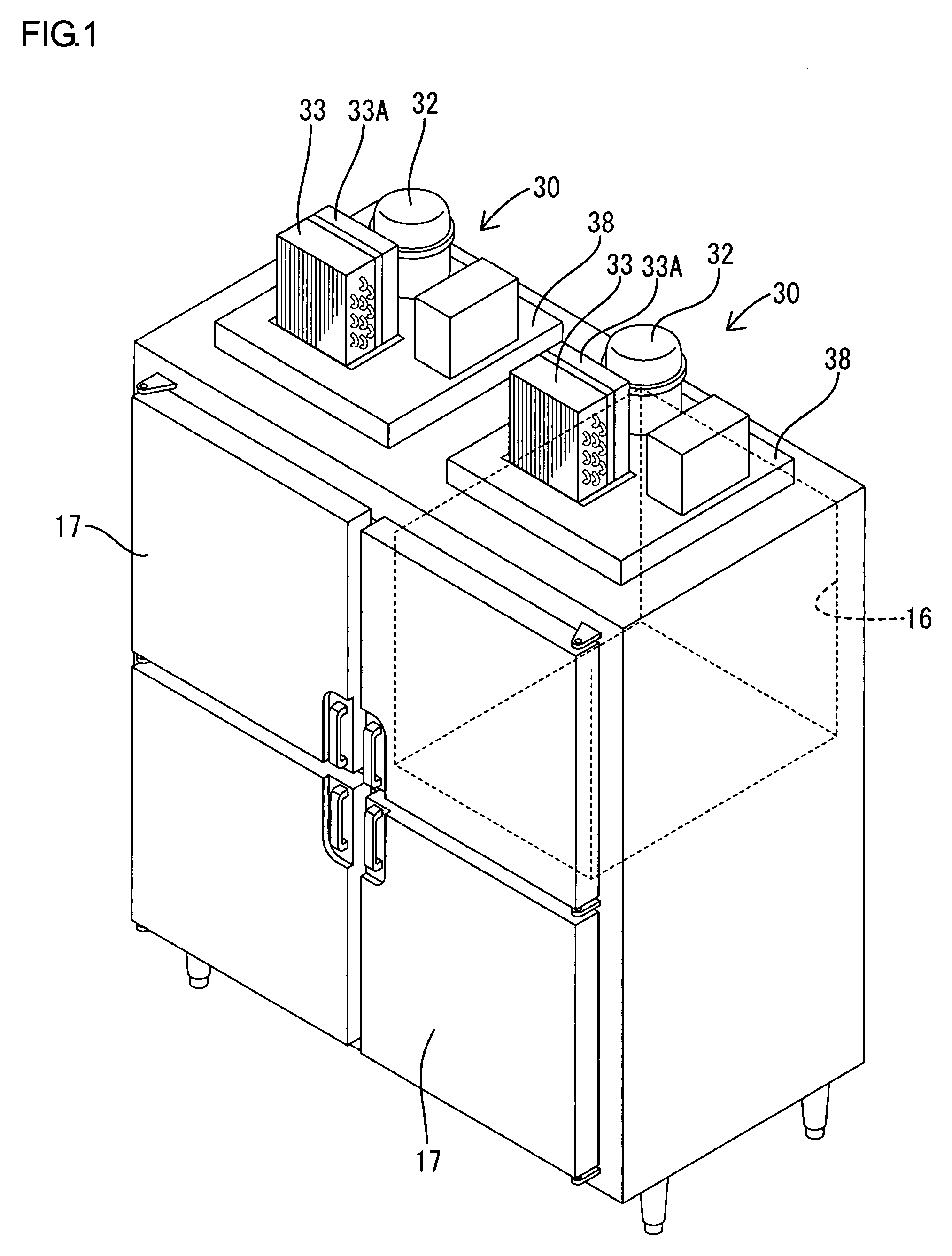
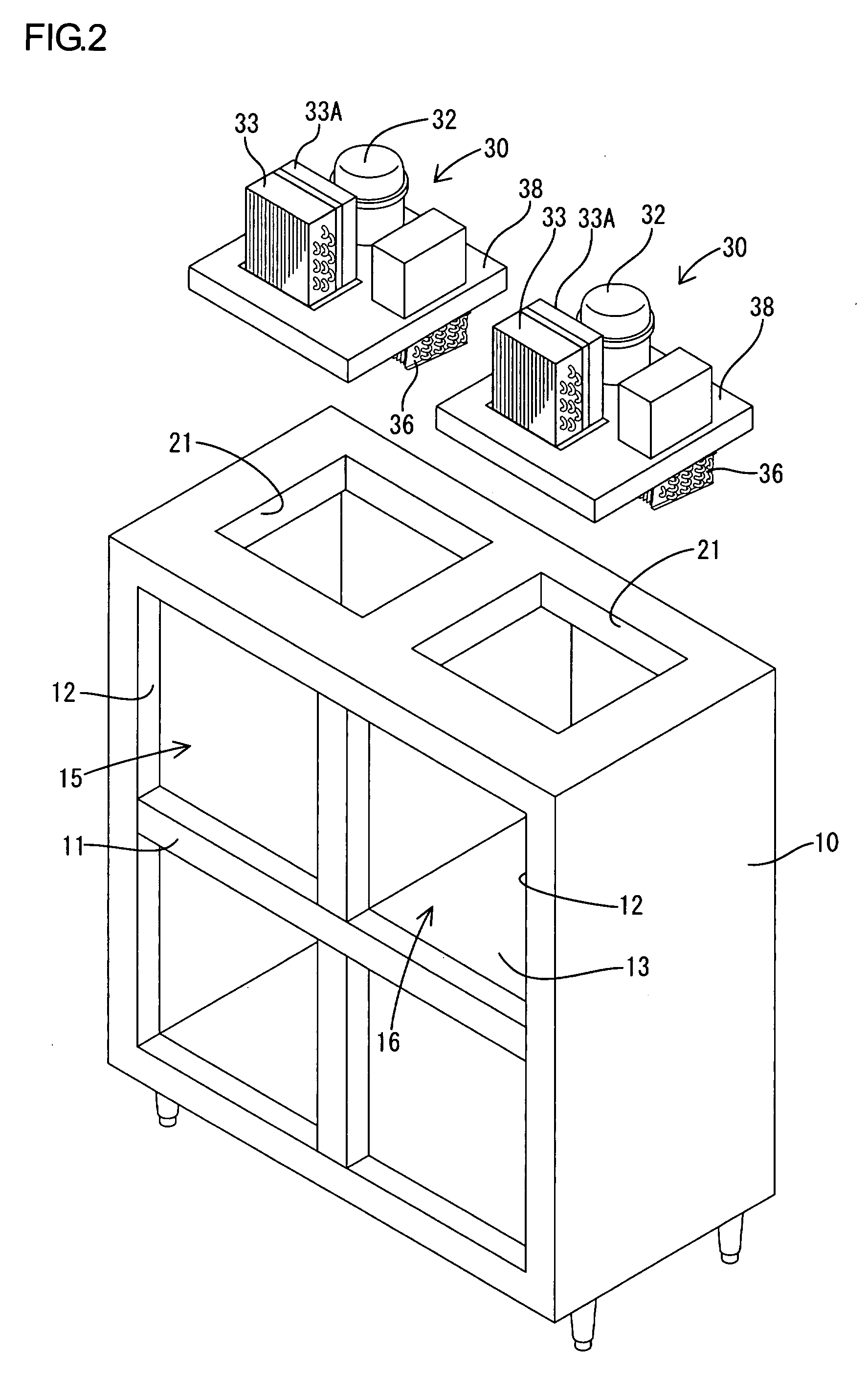
[0032]Referring to FIGS. 1 and 2, the refrigerator-freezer according to the present embodiment is a four-door type, and includes a body 10 formed of a heat insulating box having the open front as shown in FIGS. 1 and 2. The front opening is divided into four access openings 12 by a cruciform partition frame 11. The inner space is divided by a heat insulating wall 13, and thereby a freezer compartment 16 as a storage room is formed of substantially a quarter of the inner space corresponding to the upper-right access opening 12 viewed from the front. The remaining three quarters of the inner space form a refrigerator compartment 15 also as a storage room. Heat insulating doors 17 are pivotally mounted to the front of the heat insulating box so as to open and close the respective access openings 12.

[0033...

second embodiment

[0074]FIG. 7 is a flowchart of a software-related part of a controlled refrigerating operation performed by a control portion of a refrigeration unit according to a second embodiment of the present invention. The other constructions of the present embodiment are similar to the above first embodiment. Therefore, in the following explanation, the same or similar constructions are designated by the same symbols as the first embodiment, and redundant explanation is omitted.

[0075]In the above first embodiment, the control portion 50 (as the comparator) compares the measured condenser temperature Tc with the first and second reference values Tr1, Tr2. In contrast to this, according to the present embodiment, a third reference value Tr3, which is set to a value corresponding to a third predetermined pressure lower than the second predetermined pressure corresponding to the second reference value Tr2, is additionally employed. The third reference value Tr3 can be set, for example, to 68° C....

third embodiment

[0104]FIG. 8 is a flowchart of a software-related part of a controlled refrigerating operation performed by a control portion of a refrigeration unit according to a third embodiment of the present invention. The present embodiment differs from the above second embodiment in that an accumulating timer TM3 is provided for accumulating the time during which the measured value of the condenser temperature Tc exceeds the second reference value Tr2. The accumulating timer TM3 of the present embodiment corresponds to an accumulating timer of the present invention.

[0105]The other constructions of the present embodiment are similar to the above second embodiment. Therefore, in the following explanation, the same or similar constructions are designated by the same symbols as the first embodiment, and redundant explanation is omitted.

[0106]Referring to FIG. 8, the accumulating timer TM3 is reset at the initialization step S40. However the timer TM3 is not started at this time, but stopped (i.e...


PUM


Abstract

In a refrigeration unit including a variable performance compressor driven by an inverter motor, a sensor is configured to detect a physical amount corresponding to a refrigerant pressure on the high-pressure side of a refrigerant circuit. A measured value of the physical amount is compared with a first reference value corresponding to a first predetermined pressure of the refrigerant and a second reference value corresponding to a second predetermined pressure lower than the first predetermined pressure. A protective operation can start if the comparison result indicates that an actual refrigerant pressure is higher than the first predetermined pressure. The performance of the compressor can be gradually lowered if the comparison result indicates that an actual refrigerant pressure is between the first predetermined pressure and the second predetermined pressure.

Description

CROSS REFERENCE TO RELATED APPLICATION[0001]The present application is based on and incorporates herein by reference Japanese Patent Application No. 2005-82197 filed on Mar. 22, 2005.BACKGROUND OF THE INVENTION[0002]1. Field of the Invention[0003]The present invention relates to a refrigeration unit that includes a variable performance compressor.[0004]2. Description of the Related Art[0005]A refrigeration unit having a variable performance compressor is widely used for a refrigerator, a freezer, a vending machine, an ice maker, an air conditioner or the like, and the basic construction thereof is as follows. A compressor driven by an inverter motor, a condenser with a cooling fan, a throttle valve such as a capillary tube, and an evaporator, for example, are sequentially connected by a refrigerant circuit, in which a refrigerant is compressed by the compressor and thereafter cooled through the condenser, so that a cooling action is performed through the evaporator by vaporizing the...

Claims


Application Information

Patent Timeline
Patent Type & Authority Applications(United States)
IPC IPC(8): A47B96/00F25B49/00
CPCF25B49/005F25B49/025F25B49/027F25B2500/07F25B2500/19F25D29/00F25B2600/01F25B2600/021F25B2700/195F25B2700/2116F25B2500/29F25D19/04
Inventor KAGA, SHINICHIHIRANO, AKIHIKOUEDA, TAKESHI
Owner HOSHIZAKI ELECTRIC CO LTD
Why Eureka
Try Eureka