
Electrically Driven Vehicle

Inactive Publication Date: 2009-01-01
TOYOTA JIDOSHA KK
View PDF1 Cites 112 Cited by
  • Summary
  • Abstract
  • Description
  • Claims
  • Application Information

AI Technical Summary

Benefits of technology

[0007]The present invention has an object to provide an electrically driven vehicle capable of charging a main battery using a solar battery, while suppressing a decrease in the voltage of a sub-battery.
[0009]According to the first aspect, it is possible to supply a power supply voltage from the second voltage converter to the control unit. For this reason, it is possible to suppress a decrease in the amount of charge of the battery, without depleting the electrical power of the battery. It is additionally possible to mount the solar battery in a mobile unit. For this reason, it is possible to charge the battery without restriction to a specific location, such as the location of a commercial power source. Also, because a solar battery provides a DC power source, it is possible to supply electrical power to the battery without converting from AC to DC.
[0011]By doing this, it is possible by opening of the main relay at the time of charging using the solar battery to reduce the electrical power consumption of the sub-battery without regard to the charging by the drive power control unit (PCU).
[0015]By doing this, it is possible to improve the safety by separating the high-voltage parts from the low-voltage parts.
[0016]The electrically driven vehicle may further have a sub-battery that supplies a power supply voltage to an auxiliary equipment load and a monitoring unit that monitors a condition of the main battery. The monitoring unit may receive a power supply voltage from the second voltage converter in the case in which the electrical power of the solar battery is used to charge the main battery, and receive the power supply voltage from the sub-battery in during the time that the second voltage converter is stopped. For this reason, when the main battery is being charged, it is possible to operate the monitoring unit by supplying a power supply voltage from the second voltage. By doing this, because it is possible to supply a power supply voltage for the monitoring unit from the second voltage converter rather than from the sub-battery, it is possible to suppress a decrease in the amount of charge of the sub-battery by not consuming electrical power from the sub-battery.
[0020]According to the present invention, it is possible to suppress a decrease in the charge amount of the sub-battery when charging the main battery using the solar battery.

Problems solved by technology

However, if the sub-battery is depleted for the purpose of performing monitoring, for example, of the amount of sunlight when charging the main battery, even if the main battery is charged, there is the problem of a decrease in the amount of charge of the sub-battery.

Method used


Image

  • Electrically Driven Vehicle
  • Electrically Driven Vehicle
  • Electrically Driven Vehicle

Examples


Embodiment Construction

[0025]The first embodiment of the present invention is described in detail below, with references made to the accompanying drawings. Corresponding or the same elements in the drawings are assigned the same reference numerals and are not described herein.

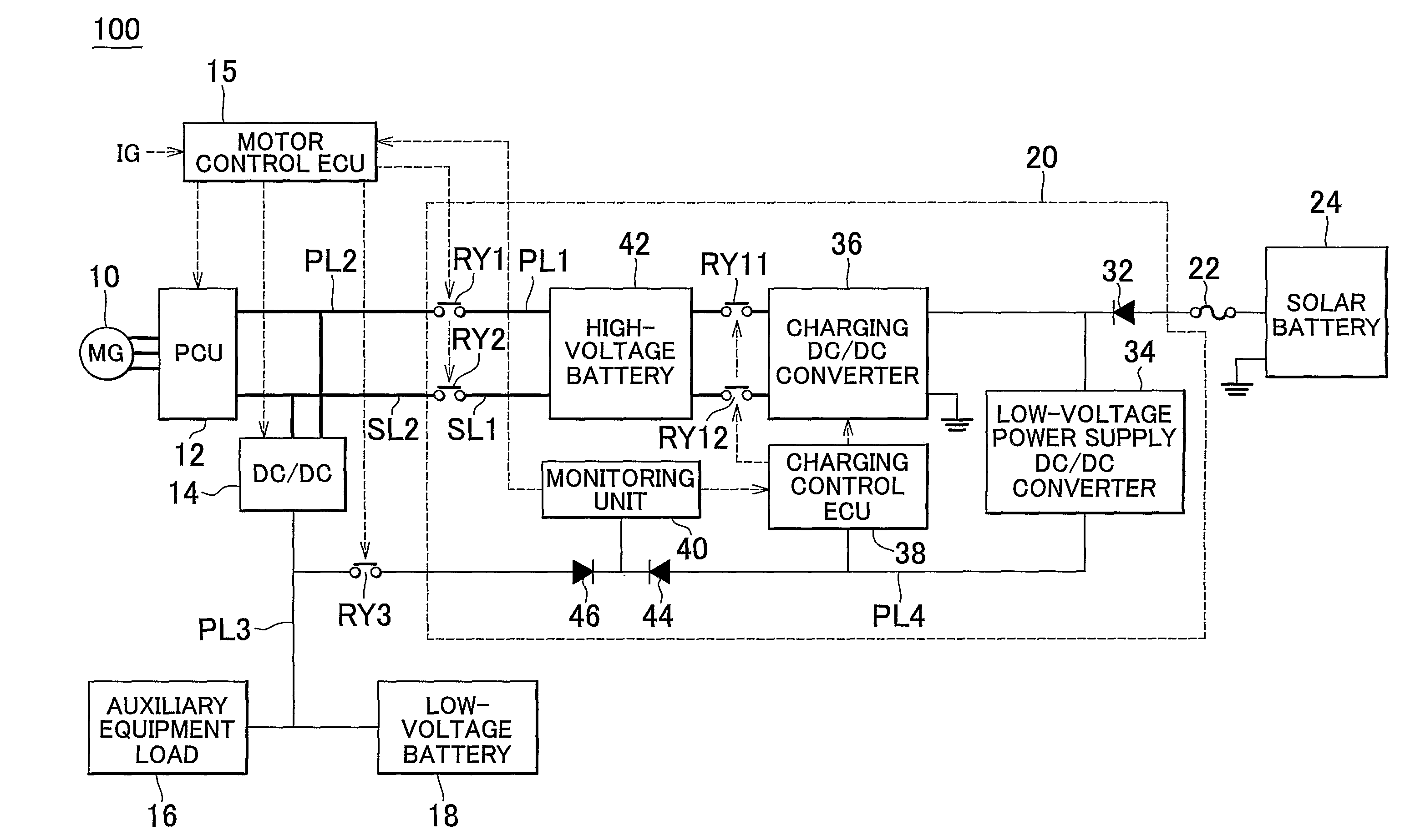
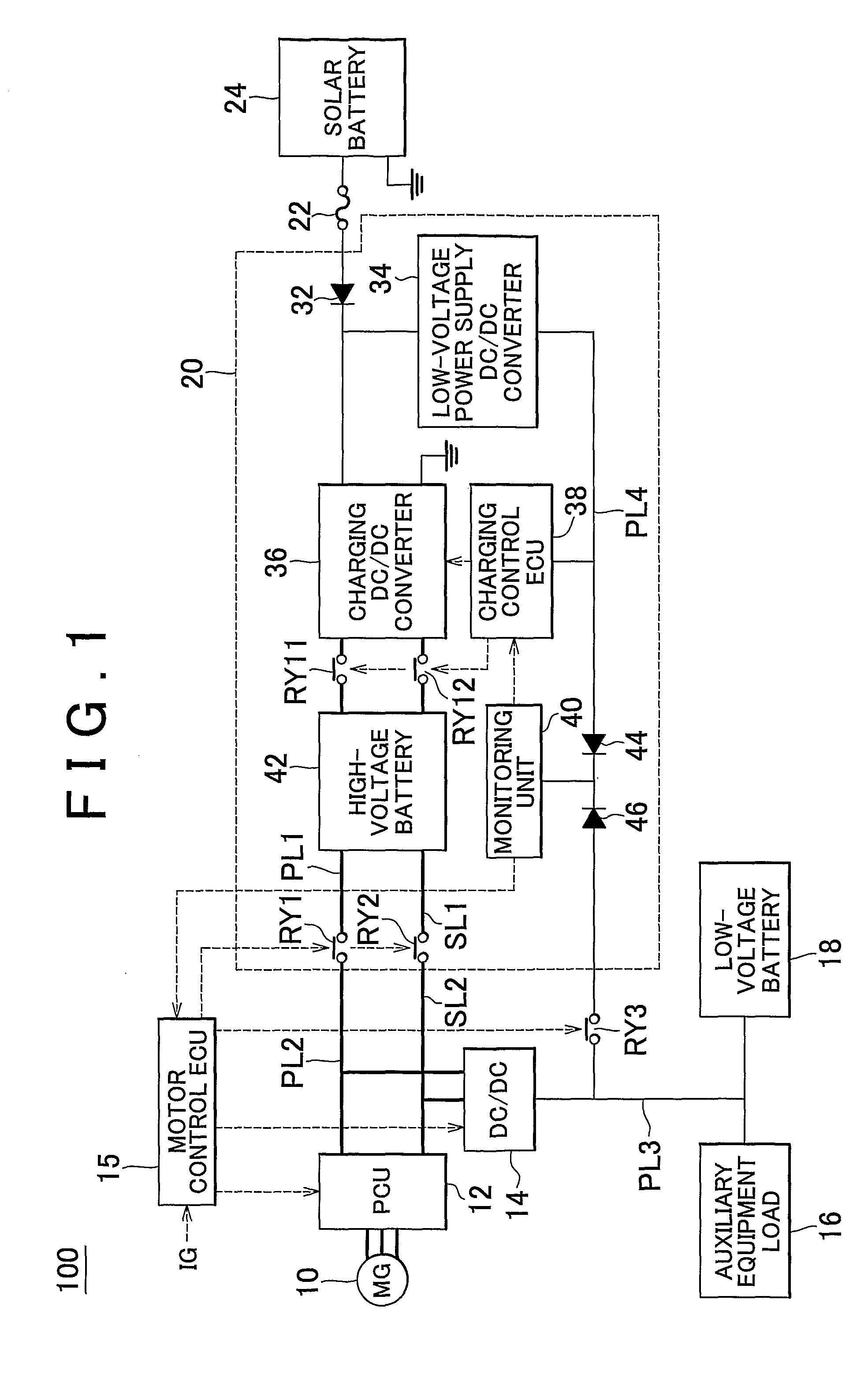
[0026]FIG. 1 is a block diagram showing the configuration of the electrically driven vehicle 100 into which is installed a solar battery charging system according to the first embodiment. This solar battery charging system is not restricted to use in an electric vehicle, and can also be applied to a hybrid vehicle having an engine and a motor and using fuel and electricity, and to other electrically driven vehicles, such as a fuel cell vehicle.

[0027]Referring to FIG. 1, the electrically driven vehicle 100 includes a high-voltage battery 42 for driving a motor 10 for driving a vehicle, a solar battery 24, a charging DC / DC converter 36 that supplies electrical power generated by the solar battery 24 to the high-voltage battery 42, a ch...


PUM


Abstract

A electrically driven vehicle (100) has high-voltage battery (42) for driving an electric motor (10) for driving the vehicle, a solar battery (24), a charging DC / DC converter (36) supplying electrical power generated by the solar battery (24) to the high-voltage battery (42), a charging control ECU (38) that performs charging control of the charging DC / DC converter (36) for charging the high-voltage battery (42), and a low-voltage power supply DC / DC converter (34) that receives a part of the electrical power generated by the solar battery (24) and generates a power supply voltage that is supplied to the charging control ECU (38).

Description

BACKGROUND OF THE INVENTION[0001]1. Field of the Invention[0002]The present invention relates to an electrically driven vehicle, and more particularly to an electrically driven vehicle in which are installed a solar battery and a storage battery.[0003]2. Description of Related Art[0004]Art related to an electrically driven vehicle has been disclosed (for example, in Japanese Patent Application Publications No. JP-A-5-111112, JP-A-11-178228, JP-A-6-78473, JP-A-2005-282428, and JP-A-5-244732). In particular, Japanese Patent Application Publication No. JP-A-5-111112 discloses an electrically driven vehicle having a main battery for driving the driving motor, an auxiliary equipment motor for driving auxiliary equipment (hereinafter “sub-battery”), a solar battery for charging the batteries, a selecting switch for selectively connecting the solar battery to the other batteries, an operation control means for causing operation of the solar battery at the point at which the electrical powe...

Claims


Application Information

Patent Timeline
IPC IPC(8): H02J7/00
CPCB60L3/0046B60L3/0053B60L8/00B60L8/003B60L11/1868Y02T90/34H02J7/35Y02T10/7005Y02T10/7066Y02T10/7083Y02T10/7216B60L2210/10B60L3/003B60L3/04B60L58/14B60L58/15B60L58/20Y02T10/70Y02T10/7072Y02T10/72
Inventor SATO, EIJI
Owner TOYOTA JIDOSHA KK
Learn More