

Method of Communication Utilizing Power Line
a technology of power line and communication method, applied in the direction of power distribution line transmission, transmission/receiving by adding signal to wave, electric controller, etc., can solve the problems of noise influence, conventional methods of communication utilizing power lin
- Summary
- Abstract
- Description
- Claims
- Application Information
AI Technical Summary
Benefits of technology
Problems solved by technology
Method used
Image

Examples
embodiment 1
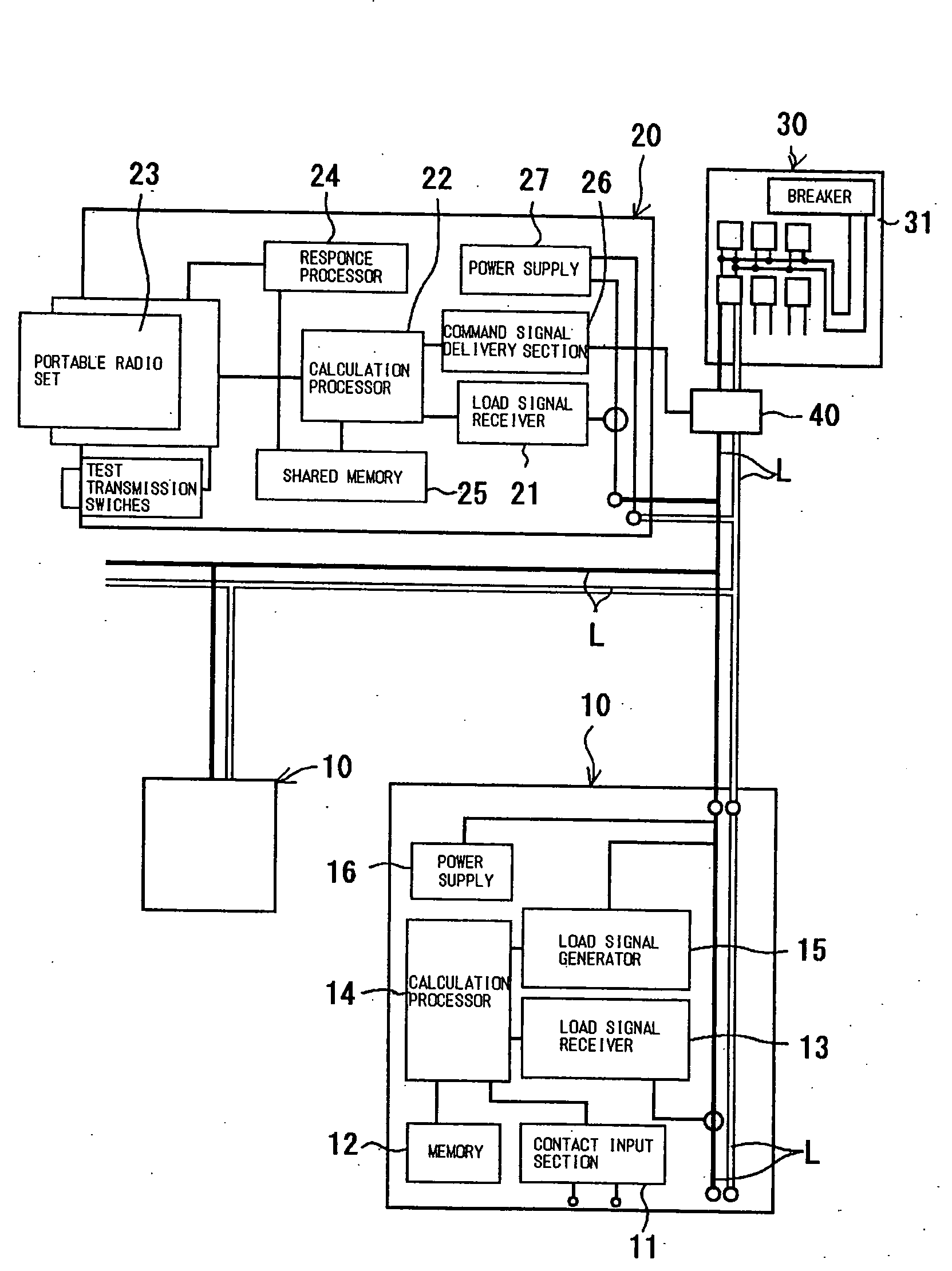
[0022]A communication system which is preferably used in the method of communication of the invention will be generally described with reference to FIG. 1. As shown in FIG. 1, for example, a communication system used in the present invention comprises a plurality of (only two shown in FIG. 1) first instruments (slave units) 10 connected to a secondary power line L which supplies a commercial power source led to a building, a general home or factory or the like, and a master unit 20 which is connected to these slave units 10 through the secondary power line L for monitoring and controlling the slave units 10. In this manner, the system is fed with a commercial AC power through the secondary power line L of a distribution board. While the master unit 20 is shown in FIG. 1 as disposed downstream of the distribution board 30, it may be connected to the secondary power line which is located upstream of the distribution board 30 (service conductors from the pole) (not shown).
[0023]In the ...
embodiment 2
[0031]FIG. 4 shows an alternating current waveform including processed waveforms which is transmitted from the slave unit 10 to the master unit 20 in this embodiment. Specifically, an arrangement is such that as shown in FIG. 4, a current value which is by a given permissible load quantity (for example, current value) ΔI higher than a peak value A of the reference waveform is previously set up as a permissible value B, and this value is stored in the shared memory 25 of the master unit 20. When the slave unit 10 applies a load signal to the secondary power line, the master unit 20 determines a normal load quantity when the peak value C of the processed waveform, which is formed by partially processing the reference waveform on the basis of the load signal is located between the peak value A and the permissible value B as shown in this Figure, and determines an abnormal load quantity for a peak value D which exceeds the permissible value B. In this manner, the master unit 20 can dete...
embodiment 3
[0032]FIG. 5 shows an alternating current waveform including processed waveforms which is transmitted from the slave unit 10 to the master unit 20 in this embodiment. In this embodiment, the magnitude of the load quantity is set up over a plurality of stages as shown, and inherent information is imparted which depends on the level of the load quantity. A load signal which corresponds to each of these load quantities is applied to the secondary power line in timed relationship with the power frequency. The amplitude of the reference waveform increases locally in response to the load signal, and the increased portion (processed waveform) is classified into a plurality of stages (or three stages in this embodiment) in accordance with the magnitude of the increase. Inherent information is imparted to each level of the increase. Specifically, the peak value of the reference waveform as shown in FIG. 5 is defined as a signal “0”. A first level L1 which is one stage higher than the peak is...
PUM
 Abstract
Description
Claims
Application Information