Liquid crystal display and driving method thereof

a technology of liquid crystal display and driving method, which is applied in the direction of electric digital data processing, instruments, computing, etc., can solve the problems of generating a large amount of current in sharp increase in dc image sticking and flickering, so as to reduce heat and power consumption of the data driving circuit, prevent degradation of picture quality, and prevent dc image sticking and flicker

Active Publication Date: 2009-01-01
LG DISPLAY CO LTD
View PDF18 Cites 20 Cited by
  • Summary
  • Abstract
  • Description
  • Claims
  • Application Information

AI Technical Summary

Benefits of technology

[0017]An object of the present invention is to provide a liquid crystal display and a driving method thereof adapted to reduce generation of heat and power consu

Problems solved by technology

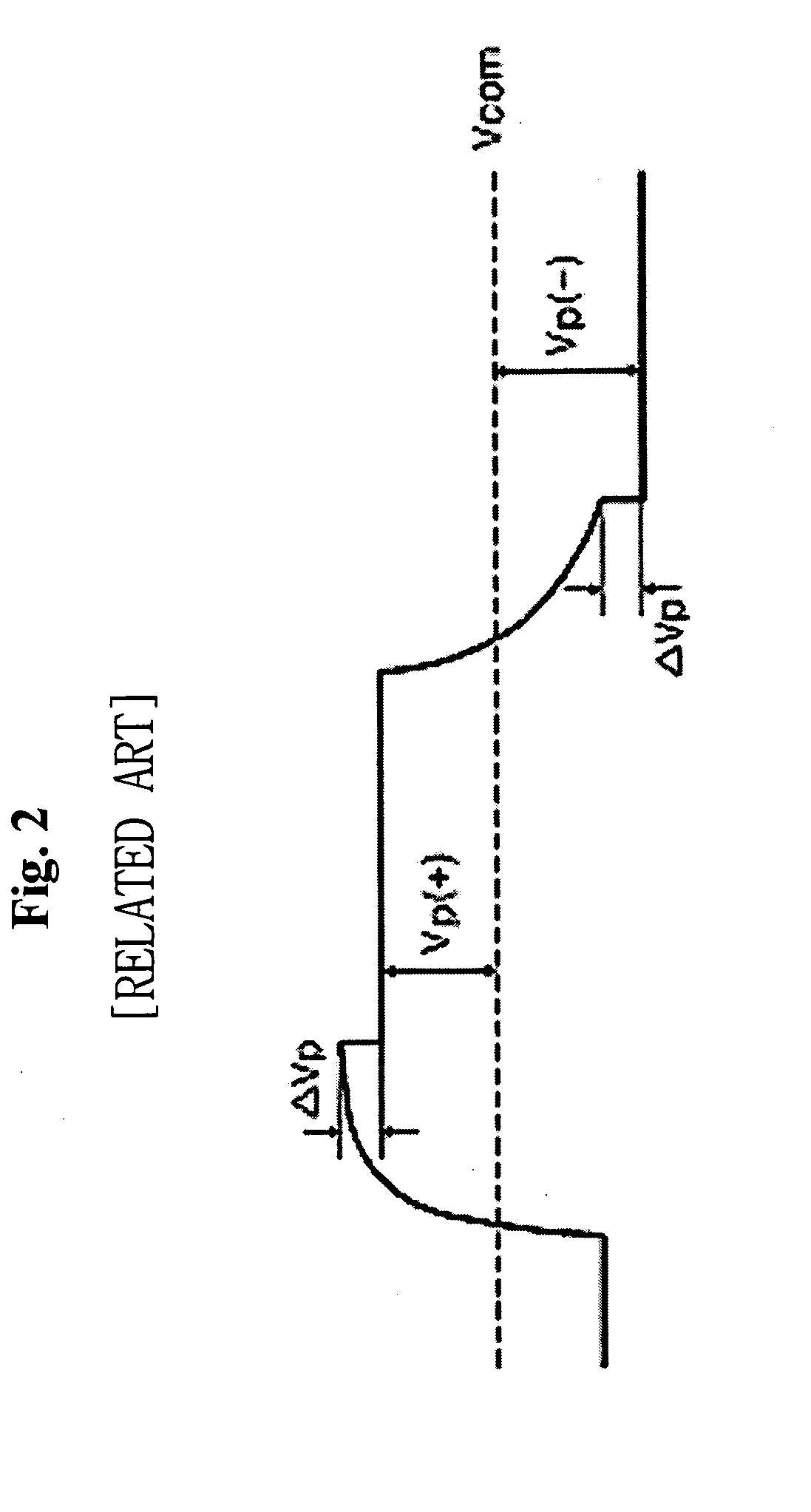
However, the swing width of the data voltage supplied to the data lines whenever the polarity of the data voltage is shifted increases, thereby generating a large amount of current in a data driving circuit.
Thus, the problems that arise include increase in heat generating temperature of the data driving circuit and sharp increase in power consumption of the data driving circuit.
However, the resulting effects are generally not satisfactory.
Thus, there is a problem that the picture quality is degraded.

Method used


Image

  • Liquid crystal display and driving method thereof
  • Liquid crystal display and driving method thereof
  • Liquid crystal display and driving method thereof

Examples


Embodiment Construction

[0040]Reference will now be made in detail to the embodiments of the present invention, examples of which are illustrated in the accompanying drawings.

[0041]FIG. 9 is a block diagram of a liquid crystal display according to an exemplary embodiment of the present invention. As shown in FIG. 9, the liquid crystal display according to the exemplary embodiment of the present invention includes a liquid crystal display panel 20, a timing controller 21, a data driving circuit 22, and a gate driving circuit 23. The liquid crystal display panel 20 has liquid crystal molecules injected between two sheets of glass substrates. M data lines D1 to Dm and n gate lines G1 to Gn are formed on a first glass substrate of the liquid crystal display panel 20 so that they cross each other. The liquid crystal display panel 20 includes (m×n) liquid crystal cells Clc disposed in matrix form by the intersecting structure of the data lines D1 to Dm and the n gate lines G1 to Gn. The data lines D1 to Dm, the ...


PUM


Abstract

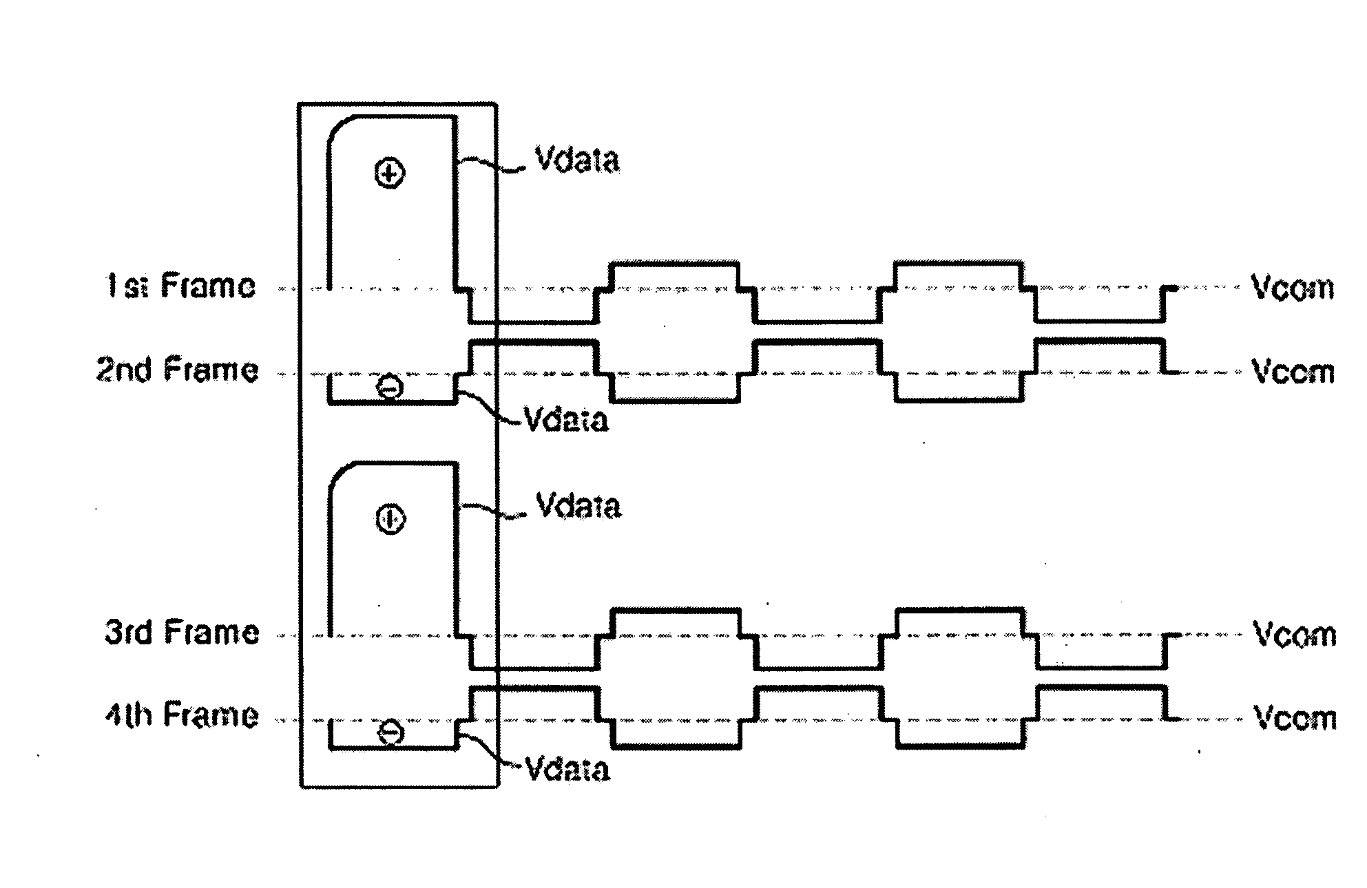
A liquid crystal display includes a liquid crystal display panel having a plurality of data lines, a plurality of gate lines, and a plurality of liquid crystal cells, a timing controller to determine gray levels of input digital video data and a time at which a polarity of a data voltage to be supplied to the data lines is inverted and generate a dynamic charge share control signal to indicate a time at which the gray level of the data voltage is changed from a white gray level to a black gray level and a time at which the polarity of the data voltage is inverted, and to detect weakness patterns in which the data of the white gray level and the black gray level are regularly arranged in the input digital video data and generate a dot inversion control signal for widening a horizontal polarity inversion time of data voltages to be supplied to the data lines when the weakness patterns are input, a data driving circuit to convert the digital video data from the timing controller into the data voltage, change the polarity of the data voltage, supply any one of a common voltage and a charge share voltage between a positive data voltage and a negative data voltage to the data lines in response to the dynamic charge share control signal, and widen the horizontal polarity inversion time of the data voltages in response to the dot inversion control signal, and a gate driving circuit to sequentially supply a scan pulse to the gate lines under the control of the timing controller, wherein the liquid crystal display panel includes first and second liquid crystal cell groups whose polarity is inverted every 2 frame periods, and a polarity inversion time of the first liquid crystal cell group and a polarity inversion time of the second liquid crystal cell group overlap.

Description

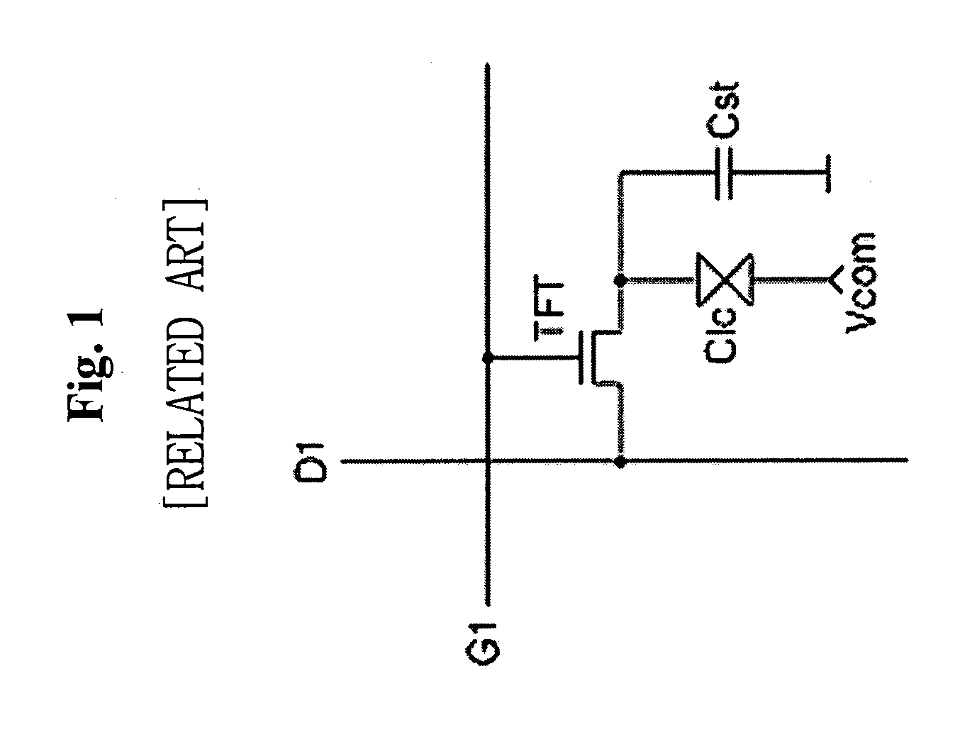
[0001]This application claims the benefit of the Korean Patent Application No. 2007-0064561 filed on Jun. 28, 2007, which is hereby incorporated by reference.BACKGROUND OF THE INVENTION[0002]1. Field of the Invention[0003]The present invention relates to a liquid crystal display, and more particularly to a liquid crystal display and a driving method thereof adapted to reduce the generation of heat and power consumption of a data driving circuit, prevent DC image sticking and flicker, and prevent degradation of picture quality when displaying data of weakness patterns.[0004]2. Discussion of the Related Art[0005]A liquid crystal display is adapted to display images by controlling the light transmittance of liquid crystal cells in response to a video signal. A liquid crystal display of an active matrix type actively controls data by switching a data voltage applied to the liquid crystal cells using a thin film transistor (TFT) formed at every liquid crystal cell Clc, as shown in FIG. 1...

Claims


Application Information

Patent Timeline
IPC IPC(8): G09G3/36G02F1/13
CPCG09G3/3614G09G3/3688G09G2360/16G09G2330/021G09G2330/023G09G2310/0248G02F1/133G09G3/36
Inventor KOO, SUNGJOJANG, SUHYUKKIM, JONGWOO
Owner LG DISPLAY CO LTD
Why Eureka
Try Eureka