Interferometer

a technology of interferometer and detector, which is applied in the field of interferometer, can solve the problems of generating vibration and not allowing simple devices, and achieve the effects of shortening the integration time of the detector, and shortening the acquisition tim

Inactive Publication Date: 2009-01-01
LAUER VINCENT
View PDF4 Cites 13 Cited by
  • Summary
  • Abstract
  • Description
  • Claims
  • Application Information

AI Technical Summary

Benefits of technology

[0025]This can be obtained by having a sufficiently small rotation of the illumination beam between each two acquisitions, less than the diffraction-limited aperture and ideally less than a fraction of the diffraction-limited aperture. Alternatively, this can be obtained by shortening the acquisition time so that the duration of the second acquisition is a fraction of the time needed for the rotation from the first to the third direction.
[0026]Shortening the acquisition time can be made by shortening the integration time of the detector. If the integration time of the detector is adjustable it should be set to less than its maximum value for the acquisition frequency (or frame rate) considered. Preferably this integration time should be less than a quarter of the duration of the rotation of the illuminating beam from the first direction to the third direction, and even more preferably it should be less than a tenth of the duration of the rotation of the illuminating beam from the first direction to the third direction.
[0027]Alternatively the interferometer may comprise a means to shut down the illumination between the first acquisition and the second acquisition, and between the second acquisition and the third acquisition. Shutting down the illumination ensures that light does not reach the detector anymore and thus shortens the acquisition time. In this case the duration of the illumination should preferably be less than the integration time of the detector.
[0028]Whichever the method employed to shorten it, the acquisition time should preferably be less than a quarter of the duration of the rotation of the illuminating beam from the first direction to the third direction, and even more preferably it should be less than a tenth of the duration of the rotation of the illuminating beam from the first direction to the third direction.

Problems solved by technology

A problem to be resolved is that in the device of patent application number PCT / FR99 / 00854 the sweeping of the directions of the illuminating beam must be made point by point; at each point the lighting direction must remain stable during a time period corresponding to the successive acquisition of three images on the camera.
The variations of the direction of the lighting beam therefore has to be step by step which generates vibrations and does not allow simple devices as mobile mirrors to obtain a fast variation of the illumination direction.

Method used


Image

  • Interferometer
  • Interferometer
  • Interferometer

Examples


Embodiment Construction

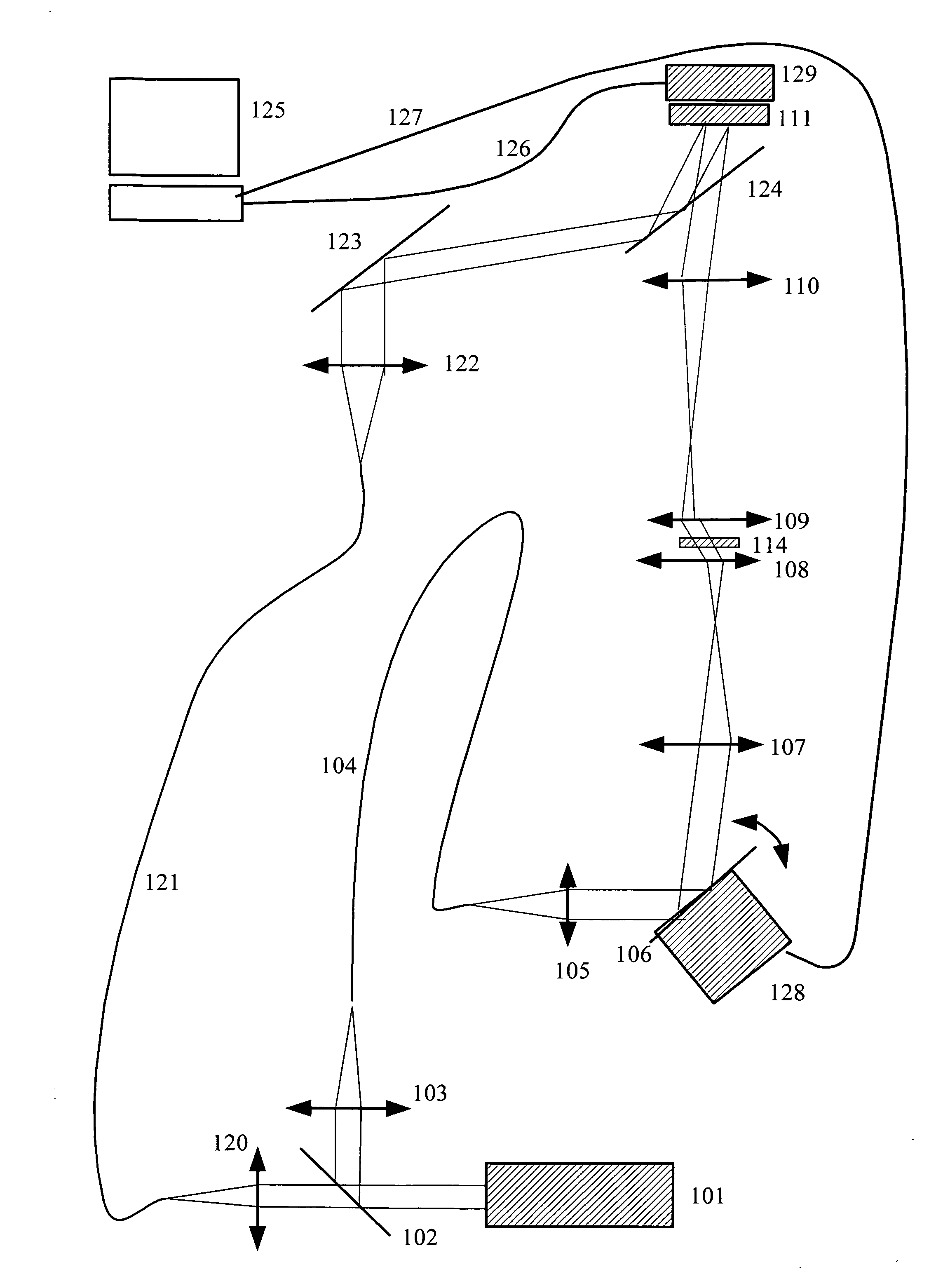
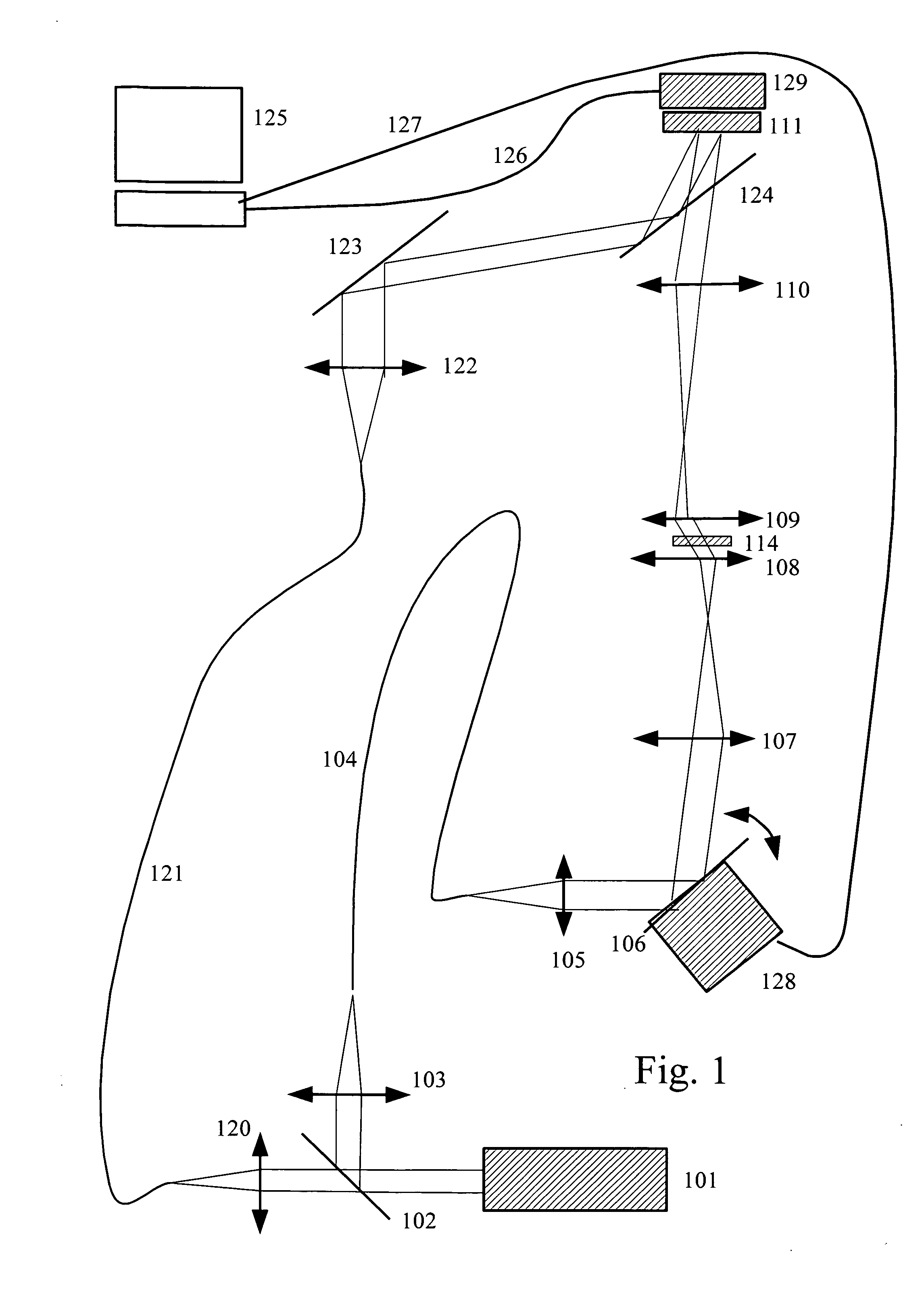
[0046]FIG. 1 shows a preferred realization. A laser 101 produces a beam which is split by a beamsplitter 102 in a reference beam and an illumination beam. The illumination beam is focused by a lens 103 on the entry of an optical fiber 104, and the reference beam is focused by a lens 120 on the entry of an optical fiber 121. The illumination beam coming out of the fiber 104 is then made parallel by a lens 105 and reflected on a mobile mirror 106 rotating around two axes. It passes through lens 107 and condenser 108 so that the illumination beam is parallel in the observed object 114. The beam diffracted by the observed object is then collected by the microscope objective 109, passes through the tube lens 110 and reaches the detector 111. The mobile mirror 106 is for example driven by two motors enclosed in a case 128 and controlled by the computer 125 through a command card (not shown) and a connection 127. The motors driving the mobile mirror may typically be stepping motors or a du...


PUM


Abstract

The interferometer of the invention comprises a moving mirror 106 for rotating the direction of an illumination beam on an observed sample 114, and a reference beam interfering with a beam diffracted by the object 114 on a detector 111. The reference beam is tilted relative to the diffracted beam.

Description

FIELD OF THE INVENTION[0001]The invention relates to an interferometer which may be used for example as a microscope or as a reader of holographic memories.STATE OF THE ART[0002]Tomographic microscopes are described for example in the patent application number PCT / FR99 / 00854 and in corresponding U.S. Pat. No. 6,525,875. These applications are included by reference in the present application. The tomographic microscope as described on FIG. 25 of patent application PCT / FR99 / 00854 needs at least three successive image acquisitions to obtain a bidimensional frequency representation representing a diffracted wave. The phase difference between the illumination beam and the reference beam must be modified between each acquisition. During the acquisition of these three images the system is highly sensitive to vibrations. Additionally the phase control of the reference wave requires costly devices when high speed acquisition is required. A number of these bidimensional frequency representati...

Claims


Application Information

Patent Timeline
Patent Type & Authority Applications(United States)
IPC IPC(8): G03H1/26
CPCG01B11/2441G01B2290/65G01B9/02032G01B9/02024
Inventor LAUER, VINCENT
Owner LAUER VINCENT
Why Eureka
Try Eureka