

Image Stabilizer
a stabilizer and image technology, applied in the field of image stabilizers, can solve problems such as camera shake and blurring of captured images, and achieve the effect of reducing the overall size and profile of an imaging apparatus
- Summary
- Abstract
- Description
- Claims
- Application Information
AI Technical Summary
Benefits of technology
Problems solved by technology
Method used
Image

Examples
embodiment 1
1. Configuration of Digital Camera
[0201]The configuration of a digital camera according to the present embodiment will be described firstly.
1-1. Overall Configuration
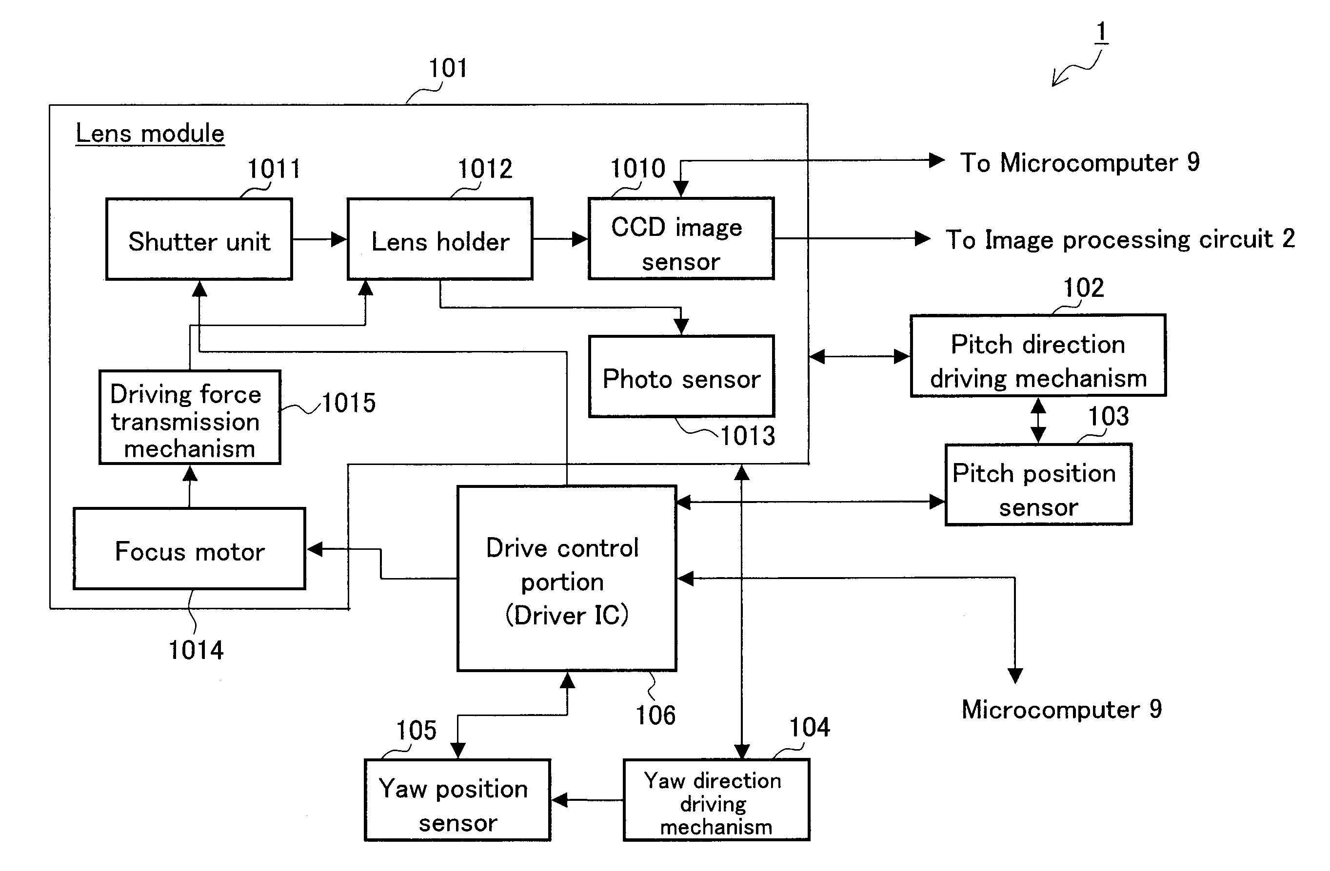
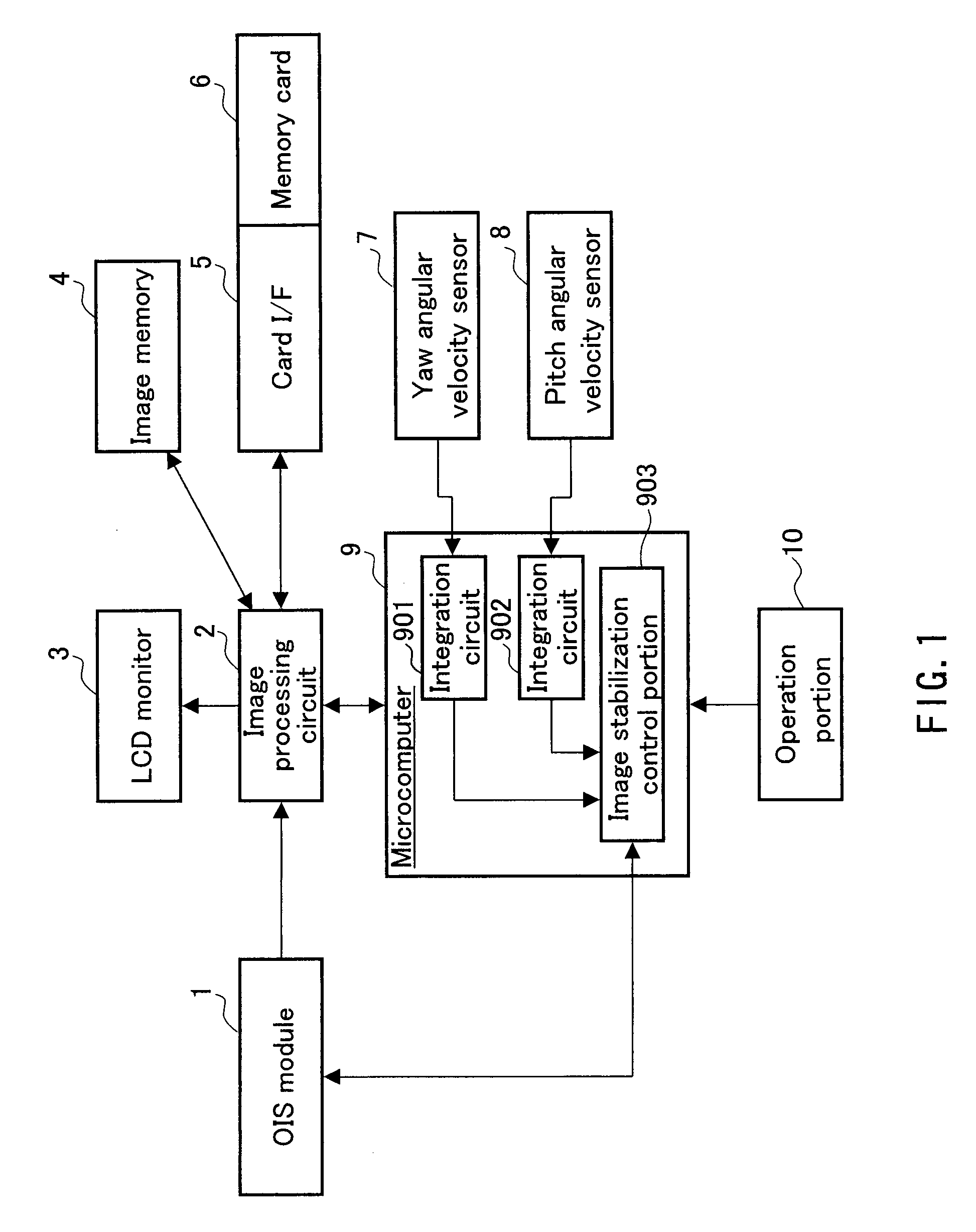
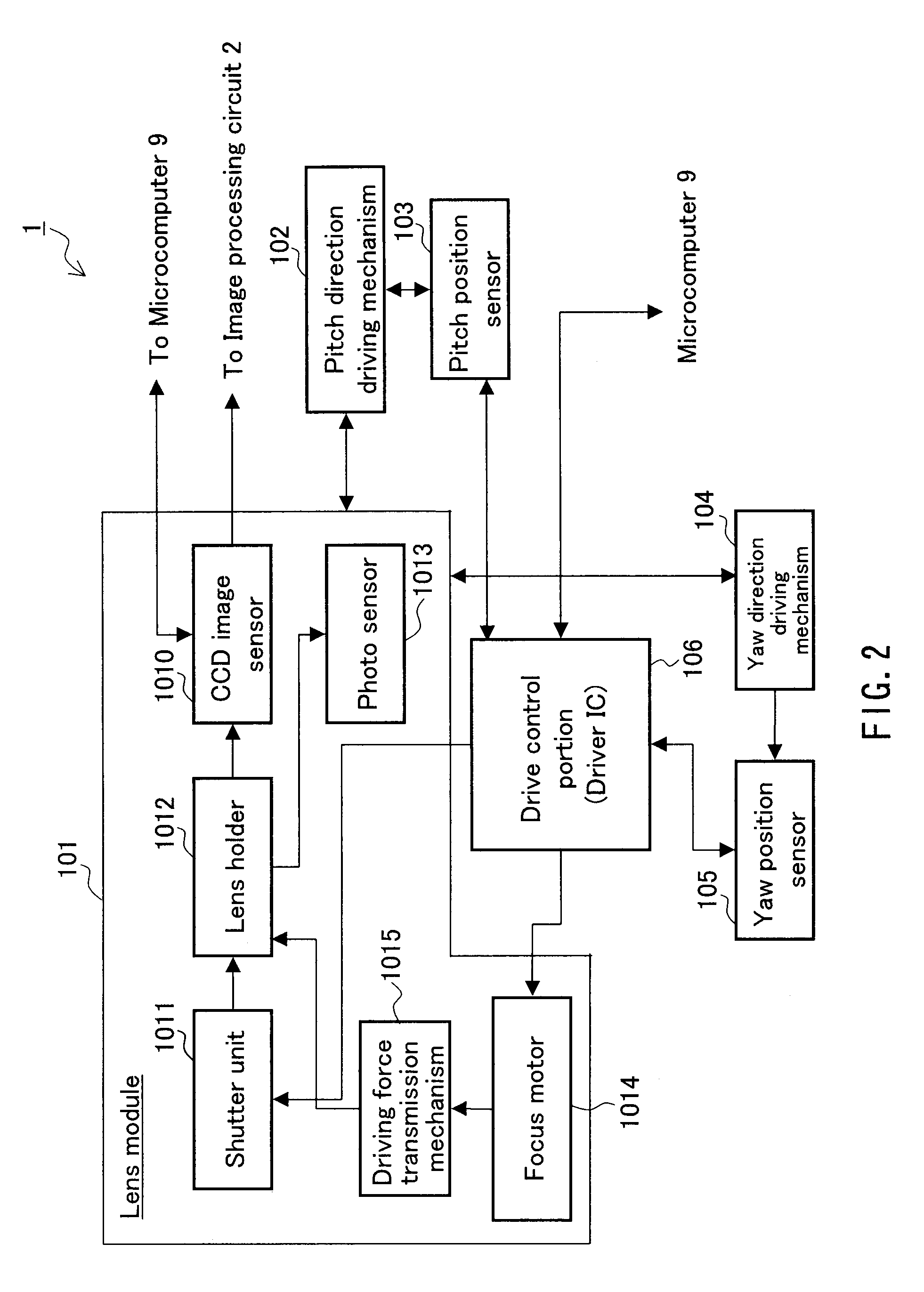
[0202]FIG. 1 is a block diagram showing the configuration of a digital camera according to the present embodiment. The digital camera of the present embodiment includes an OIS (optical image stabilizer) module 1, an image processing circuit 2, an LCD (liquid crystal display) monitor 3, an image memory 4, a card interface 5, a memory card 6, a yaw angular velocity sensor 7, a pitch angular velocity sensor 8, a microcomputer 9, and an operation portion 10.
[0203]The OIS module 1 includes a CCD image sensor (described later). The image processing circuit 2 performs image processing such YC conversion, resolution conversion, and compression conversion on image data generated by the CCD image sensor. The LCD monitor 3 displays image data processed by the image processing circuit 2. The image memory 4 functions as a buffer mem...
embodiment 2
[0398]An embodiment 2 of the present invention will be described next. Note that in embodiment 2, the same reference numerals are associated with constituent elements that are similar to the aforementioned embodiment 1, and a detailed description of these elements will be omitted. The following description will focus on the differences from the configuration of embodiment 1.
1. Control of Digital Camera
1-1. Overall Operations
[0399]FIG. 49 is a block diagram showing a schematic configuration of the control system of a digital camera according to the present embodiment. As shown in FIG. 49, the drive control portion 106 of the OIS module 1 includes an amplitude subtraction portion 1061, an integration circuit 1071, an amplitude subtraction portion1073, a lead lag filter 1063, an amplifier circuit 1065, and a step-up circuit 1067 for position control about the yaw turning axis Y, and an amplitude calculation portion 1062, an integration circuit 1072, an amplitude subtraction portion 107...
embodiment 3
[0447]Connecting Piezoelectric Element to Drive Body (1)
[0448]FIG. 56 is a perspective view of an assembly body for driving an entire lens barrel that includes an imaging element such as a CCD, illustrating the connection between a piezoelectric element and a drive body according to an embodiment of the present invention. FIGS. 57 and 58 are enlarged views illustrating in details the connecting portion between the piezoelectric element and the drive body and configuration thereof.
[0449]In FIG. 56, a lens barrel 3001 integrated with a lens barrel base 3001a is adhered to a drive frame 3003, and an imaging element 3002 such as a CCD is disposed below the lens barrel 3001. The drive frame 3003 is supported turnably on a turning axis 3014 by a fixing frame 3004 that has two bearings 3003a (one not shown) opposed at right angles to an optical axis 3013. A piezoelectric element 3005 (so-called bimorph) is attached below the fixing frame 3004, that is, below the imaging element 3002 with s...
PUM
 Abstract
Description
Claims
Application Information