Substrate retaining ring for CMP

a technology of retaining rings and substrates, applied in the field of retaining rings, can solve the problems of adversely affecting the yield and/or reliability of devices fabricated on the substrate, becoming increasingly difficult to form features with high dimensional accuracy, etc., and achieves the effects of reducing the edge effect or irregular edge polishing profile of the substrate, reducing the edge effect or uneven edge polishing profile, and reducing the edge

Active Publication Date: 2009-10-06
IV TECH CO LTD
View PDF22 Cites 2 Cited by
  • Summary
  • Abstract
  • Description
  • Claims
  • Application Information

AI Technical Summary

Benefits of technology

[0006]An advantage of the present invention is a retaining ring structured to eliminate or substantially reduce the edge effect or irregular edge polishing profile of a substrate undergoing CMP.
[0007]Another advantage of the present invention is a method of planarizing a substrate by CMP without or with a reduced edge effect or uneven edge polishing profile.
[0008]According to the present invention, the foregoing and other advantages are achieved in part by a retaining ring for accommodating a substrate during chemical mechanical polishing (CMP), the retaining ring having an outer surface and an inner surface such that a width from the inner surface to the outer surface in a radial direction varies in an amount sufficient to substantially reduce an edge effect by causing an edge polishing profile to shift back and forth toward the center of the substrate as the width varies during CMP.
[0009]Another advantage of the present invention is a retaining ring having an outer surface with a geometric center and an inner surface with a geometric center, wherein the geometric centers of the inner and outer surfaces are offset.
[0010]A further advantage of the present invention is a retaining ring having an inner surface, accommodating a substrate about its periphery, and an outer surface, wherein the distance between the outer surface to the perimeter of the substrate varies in a radial direction.
[0011]A further advantage of the present invention is a retaining ring having an inner surface with a geometric center and an outer surface, wherein a distance from the outer surface to the geometric center of the inner surface varies in a radial direction.

Problems solved by technology

As the dimensions of semiconductor device features continue to shrink into the deep submicron range, it becomes increasingly more difficult to form the features with high dimensional accuracy.
A problem attendant upon conventional CMP is known as the “edge effect”, which is the tendency of the edge of the substrate to be polished at a rate different from the polishing rate at the center of the substrate.
Thus, the edge effect typically results in either removing too much material from the substrate at the perimeter (overpolishing) and / or failing to remove sufficient material from the outer perimeter of the substrate (underpolishing) vis-à-vis the remainder of the substrate, resulting in an uneven edge polishing profile, thereby adversely impacting yield and / or reliability of devices fabricated on the substrate.

Method used


Image

  • Substrate retaining ring for CMP
  • Substrate retaining ring for CMP
  • Substrate retaining ring for CMP

Examples


Embodiment Construction

[0029]The present invention addresses and solves problems attendant upon conventional retaining rings employed to retain a substrate in a retaining head during CMP. The use of conventional retaining rings results in what is known as the edge effect manifested by a difference in the polishing rate profile between the edge of a substrate undergoing CMP and a remainder of the substrate resulting in irregular edge planarity leading to decreased yield. Although previous attempts have been made to address the edge effect, such efforts have not been sufficient to adequately fulfill the increasing requirements for precise submicron device technology.

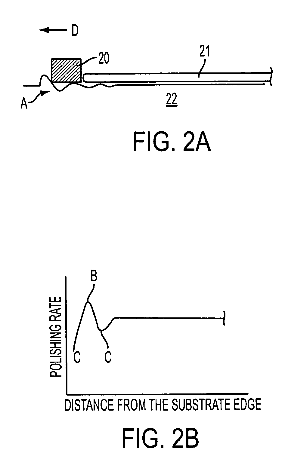
[0030]Adverting to FIG. 2, it was found that the edge profile problem stems from the pressure exerted by a conventional retaining ring 20, accommodating substrate 21, against polishing pad 22 during CMP, resulting in surface deformation A at the edge of polishing pad 22. Reference character D denotes the direction of movement with respect to pol...


PUM

PropertyMeasurementUnit
diameteraaaaaaaaaa
diameteraaaaaaaaaa
diameteraaaaaaaaaa

Abstract

The edge effect or variation in polishing edge profile on a substrate undergoing CMP is reduced by structuring a retaining ring, housed in a carrier head for retaining the substrate, such that the polishing edge profile shifts back and forth with respect to the center of the substrate. Embodiments include structuring the retaining ring such that the width between inner and outer surfaces varies by an amount sufficient to compensate for polishing edge profile variation. Embodiments also include structuring the retaining ring such that the distance from the outer surface to the geometric inner surface varies. Embodiments further include structuring the retaining ring such that the distance between the outer surface to the perimeter of the substrate retained by the inner surface of the retaining ring varies.

Description

FIELD OF THE INVENTION[0001]The present invention relates to retaining rings for retaining a substrate during chemical mechanical polishing (CMP). The present invention is particularly applicable to retaining rings for use in CMP to obtain substrates with improved uniform planarity.BACKGROUND ART[0002]As the dimensions of semiconductor device features continue to shrink into the deep submicron range, it becomes increasingly more difficult to form the features with high dimensional accuracy. The minimum size of a feature depends upon the chemical and optical limits of a particular lithography system, notably the depth of focus of a particular tool. Therefore, it is of utmost importance to provide an extremely flat wafer or substrate surface during fabrication of integrated circuits as well as other electronic devices.[0003]Conventional practices include planarizing a substrate surface to remove high topography by CMP, which typically involves introducing a chemical slurry during poli...

Claims


Application Information

Patent Timeline
Patent Type & Authority Patents(United States)
IPC IPC(8): B24B7/22
CPCB24B37/32
Inventor WANG, YU-PIAO
Owner IV TECH CO LTD
Why Eureka
Try Eureka