Superconducting Magnetic Coil with a Quench Protection Circuit, and Mrt Apparatus Embodying Same

a technology of protection circuit and superconducting magnetic coil, which is applied in the direction of emergency protection circuit arrangement, emergency protection arrangement for limiting excess voltage/current, electric devices, etc., can solve the problems of mrt apparatus components being exposed to considerable forces, damage components of cryomagnets, and collapse of the magnetic field developed by this current, etc., to achieve a simple and cost-effective circuit

Inactive Publication Date: 2009-01-01
SIEMENS AG
View PDF6 Cites 9 Cited by
  • Summary
  • Abstract
  • Description
  • Claims
  • Application Information

AI Technical Summary

Benefits of technology

[0015]An object of the present invention a superconducting magnetic coil with a circuit for quench protection in which problems described above in a quench and upon charging or discharging of the magnet can be avoided with a simple, cost-effectively produced circuit. Furthermore, it is an object of the invention to specify an MRT apparatus with such a superconducting coil.

Problems solved by technology

Due to the non-zero electrical resistance, the current flow in the magnetic coil changes and the magnetic field developed by this current collapses.
The collapse of the magnetic field causes a series of events, of which each entails a problem.
If only a small region of the magnetic coil (for example only one sub-coil) is normally-conductive, this can lead to the situation that the released energy in the locally limited region is transduced into thermal energy, which in turn leads to a severe local overheating that can damage components of the cryomagnet.
Moreover, eddy currents that in turn interact with the magnetic field arise due to the changing magnetic field in the magnetic coil and in other conductive components of the MRT apparatus, such that components of the MRT apparatus are exposed to considerable forces.
Furthermore, the current flow I changes relatively severely in a short time.
Without further protective measures, these voltage excesses can lead to damage to the coil and / or to the insulation of the coil.
The use of resistors does in fact solve the problems that can occur in a quench, but the use of resistors also entails disadvantages that predominantly appear during the phase of the charging, and discharging of the magnetic coils.
In addition to increased costs due to the vaporized helium, quenches can also occur.
Although the heating can be reduced by using higher-impedance resistors, the use of higher-impedance resistors in turn holds the danger of higher voltage excesses given a quench.
However, the employed arrangement of the diodes is not suitable to control a quench or to keep its propagation symmetrical.
However, both shown circuits appear to be relatively complicated in terms of their construction due to the use of different electrical and electronic components.

Method used


Image

  • Superconducting Magnetic Coil with a Quench Protection Circuit, and Mrt Apparatus Embodying Same
  • Superconducting Magnetic Coil with a Quench Protection Circuit, and Mrt Apparatus Embodying Same
  • Superconducting Magnetic Coil with a Quench Protection Circuit, and Mrt Apparatus Embodying Same

Examples


Embodiment Construction

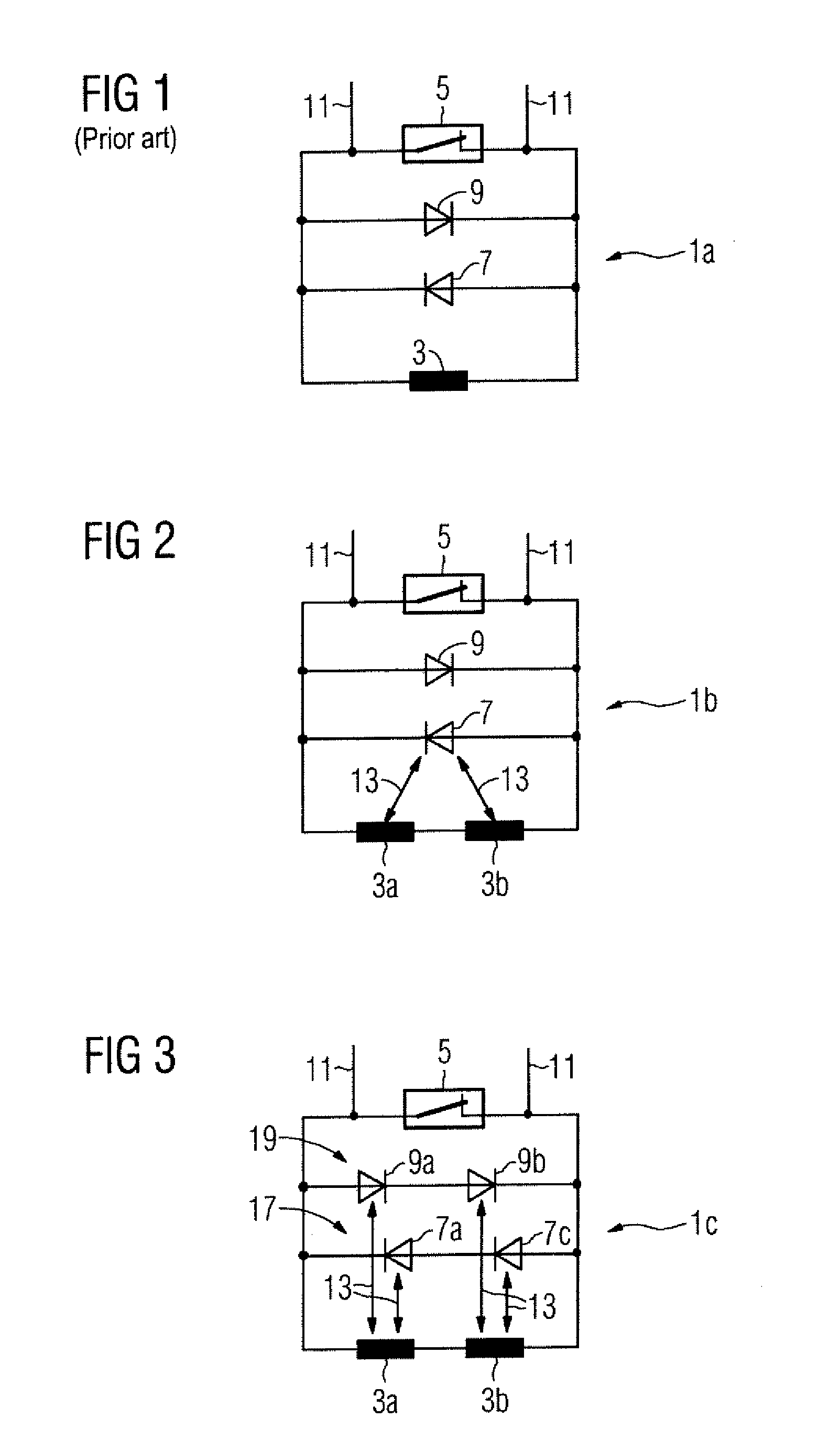
[0041]FIG. 1 shows the basic design of a superconducting magnetic coil with two diodes connected in anti-parallel.

[0042]A diode circuit operated according to the principle presented in the following was used in a cryomagnet of the Helicon type from Siemens AG. In contrast to the design presented here, this magnetic coil does in fact comprise multiple sub-coils spatially separated from one another and multiple diodes connected in parallel for this; however, the principle design is not the same.

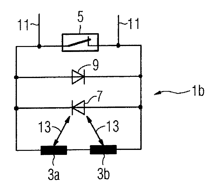
[0043]The primary component of the magnetic coil 1a is a sub-coil 3 with which the basic magnetic field is generated. If the magnetic coil 1a is located in an already-charged state, the current circulates without loss in the resistance-free superconducting conductor wires. As shown here the superconducting 5 is thereby in the closed state. The superconducting conductor wires typically are formed of a niobium-titanium alloy or a niobium-tin alloy with a copper jacket, such that they are supercon...


PUM


Abstract

A superconductive magnetic coil arrangement has a superconducting magnetic coil and a circuit for quench protection. The quench protection circuit includes at least one diode connected in parallel with a portion of the superconductive magnetic coil. The at least one diode is in thermal contact with the superconductive magnetic coil A magnetic resonance tomography apparatus embodies such a magnetic coil arrangement.

Description

[0001]The present invention concerns a superconducting magnetic coil with a circuit for quench protection, as is used in magnetic resonance tomography apparatuses (designated in the following as MRT apparatuses), as well as an MRT apparatus embodying such a magnetic coil.DESCRIPTION OF THE PRIOR ART[0002]As is known, a magnetic coil made from a superconducting material can be operated in a superconducting state when the magnetic coil is located in a very cold environment such as, for example, in a cryotank filled with liquid helium. In the superconducting state the coil wires has practically no resistance, such that no energy is required to maintain a current flow in the magnetic coil and therefore also to maintain the magnetic field generated by the magnetic coil. The current flow itself is actively fed into the coil during a process known as a charging procedure before start-up of the magnet. Such cryomagnets have found wide use in MRT apparatuses.[0003]An MRT cryomagnet conventio...

Claims


Application Information

Patent Timeline
Patent Type & Authority Applications(United States)
IPC IPC(8): H02H7/00
CPCY02E40/68H02H7/001Y02E40/60
Inventor BITTNER, GERHARD
Owner SIEMENS AG
Why Eureka
Try Eureka