Power Supply Device, Electrically-Driven Vehicle Incorporating Power Supply Device, and Method of Controlling Power Supply Device

a technology of power supply device and power supply device, which is applied in the direction of power supply testing, battery/fuel cell control arrangement, instruments, etc., can solve the problems of inaccurate detection of the decrease in the insulation resistance of the power supply device, and the inability to take into account the effect of the capacitive component of the commercial power supply load, etc., to achieve accurate detection of the decrease in the insulation resistance

Inactive Publication Date: 2009-01-01
TOYOTA JIDOSHA KK
View PDF4 Cites 28 Cited by
  • Summary
  • Abstract
  • Description
  • Claims
  • Application Information

AI Technical Summary

Benefits of technology

[0005]The present invention is directed to solve the above-described problem. An object of the present invention is to provide a power supply device capable of accurately detecting the decrease in the insulation resistance.
[0006]Furthermore, another object of the present invention is to provide an electrically-driven vehicle which incorporates a power supply device capable of accurately detecting the decrease in the insulation resistance.
[0007]Still another object of the present invention is to provide a method of controlling a power supply device capable of accurately detecting the decrease in the insulation resistance.
[0021]Therefore, according to the present invention, the decrease in the insulation resistance can be accurately detected.

Problems solved by technology

In the above-mentioned Japanese Patent Laying-Open No. 10-290529, however, the variations in impedance due to the effect of the capacitive component of the commercial power supply load is not taken into consideration.
Thus, the decrease in insulation resistance of the power supply device cannot be accurately detected.

Method used


Image

  • Power Supply Device, Electrically-Driven Vehicle Incorporating Power Supply Device, and Method of Controlling Power Supply Device
  • Power Supply Device, Electrically-Driven Vehicle Incorporating Power Supply Device, and Method of Controlling Power Supply Device
  • Power Supply Device, Electrically-Driven Vehicle Incorporating Power Supply Device, and Method of Controlling Power Supply Device

Examples


first embodiment

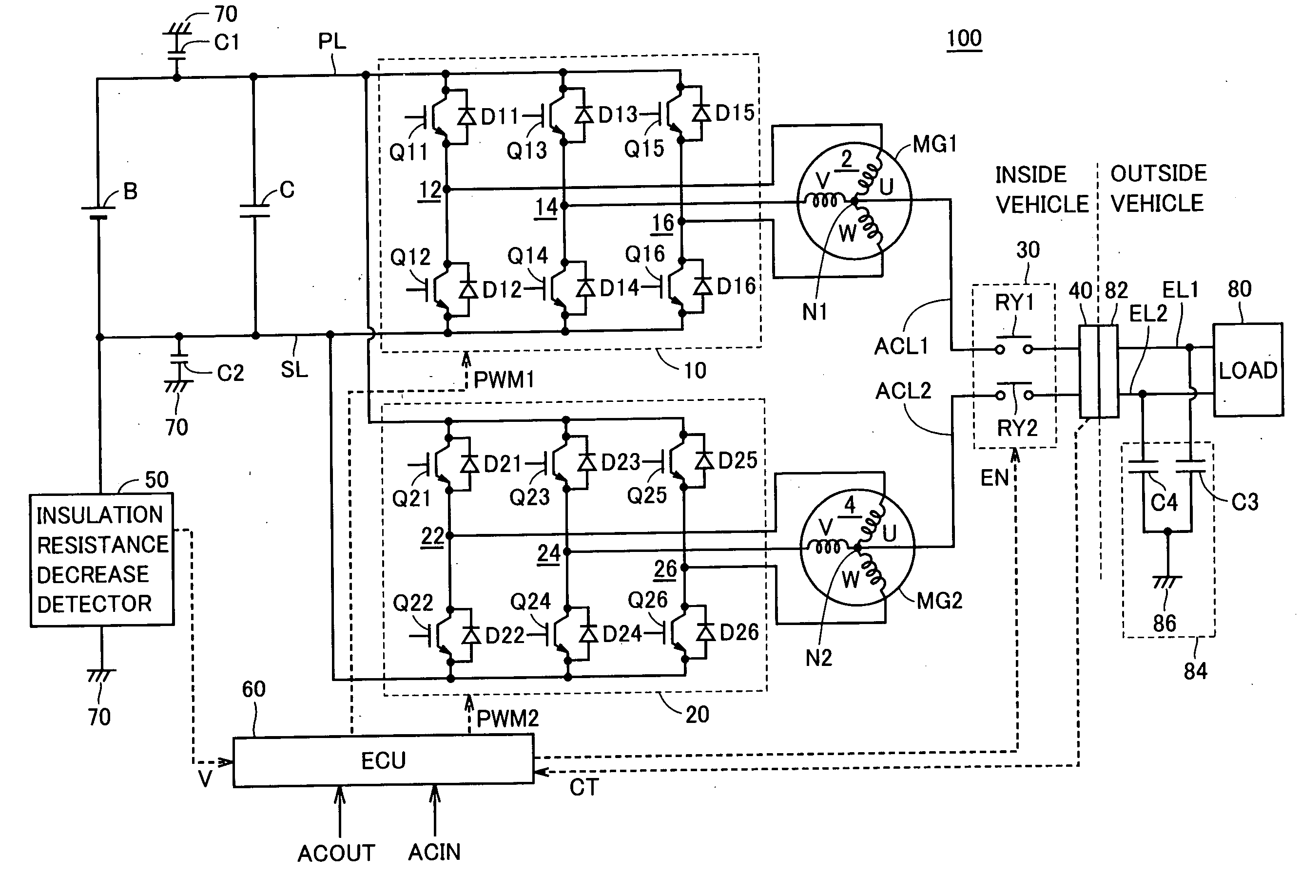
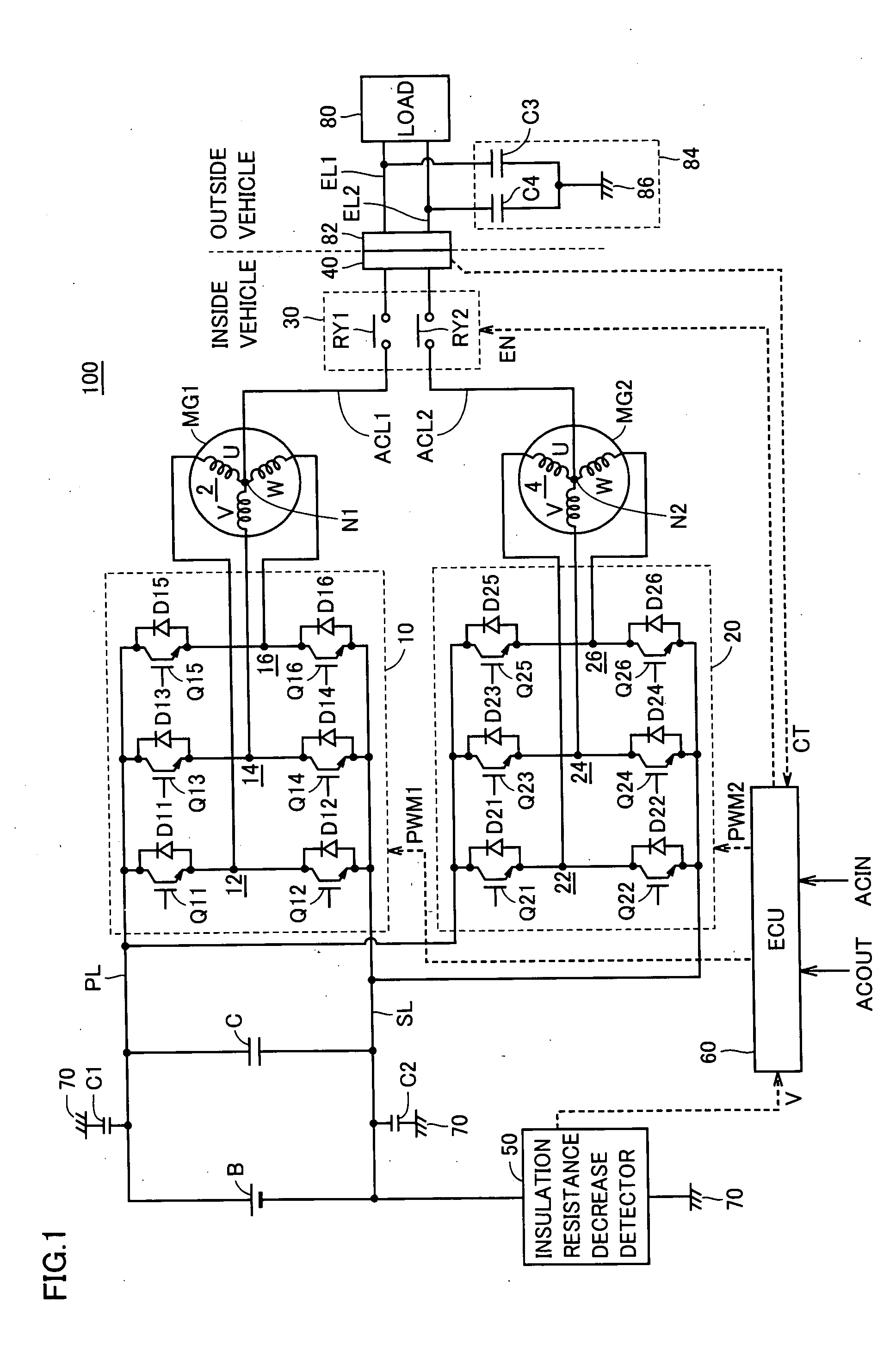
[0034]FIG. 1 is an overall block diagram of a power supply device according to the first embodiment of the present invention. Referring to FIG. 1, the power supply device 100 includes a power storage device B, a smoothing capacitor C, inverters 10 and 20, motor generators MG1 and MG2, a power supply line PL, and a ground line SL. Power supply device 100 also includes AC lines ACL1 and ACL2, a relay circuit 30, a connector 40, an insulation resistance decrease detector 50, and an electronic control unit (also referred to as an “ECU” hereinafter) 60.

[0035]Power supply device 100 is incorporated into a hybrid vehicle. Motor generator MG1 is incorporated into the hybrid vehicle as one that operates as an electric motor capable of starting an engine (not shown) and operates as an electric generator driven by the engine. Motor generator MG2 is incorporated into the hybrid vehicle as an electric motor driving the driving wheels of the hybrid vehicle (not shown).

[0036]The hybrid vehicle inc...

second embodiment

[0088]During vehicle running (that is, the state where load 80 external to the vehicle is not connected to power supply device 100), power storage device B is charged and discharged frequently, and voltage V from insulation resistance decrease detector 50 varies accordingly. On the other hand, at the time of transmission and reception of the electric power between power supply device 100 and load 80 external to the vehicle (that is, the state where load 80 external to the vehicle is connected to power supply device 100), power storage device B is not frequently charged and discharged as during vehicle running. Therefore, voltage V is stable.

[0089]Thus, in the second embodiment, in order to prevent erroneous detection resulting from variations in voltage V, the decrease in the insulation resistance is defined when the decrease in the detected peak value continues for a predetermined period of time. When load 80 external to the vehicle is electrically connected to power supply device ...


PUM


Abstract

An ECU determines based on a voltage from an insulation resistance decrease detector whether the insulation resistance of a power supply device decreases or not. When a load external to the vehicle is not connected to the power supply device, the ECU sets a determination threshold value for determining that the insulation resistance decreases to a normal first value. On the other hand, when the load external to the vehicle is electrically connected to the power supply device, the ECU sets the determination threshold value to a second value which is lower than the first value, in consideration of an increase in the capacitive component due to a capacitor of a Y-capacitor.

Description

TECHNICAL FIELD[0001]The present invention relates to a power supply device incorporated in an electrically-driven vehicle, the electrically-driven vehicle incorporating the power supply device, and a method of controlling the power supply device incorporated in the electrically-driven vehicle.BACKGROUND ART[0002]Japanese Patent Laying-Open No. 10-290529 discloses a power supply device incorporated in an electric vehicle. The power supply device includes a battery, an electric circuit system such as a running motor and an on-vehicle auxiliary machine supplied with power from the battery, an inverter circuit for generating a commercial alternating-current (AC) voltage that converts a direct-current (DC) voltage from the battery to a commercial AC voltage for application to a commercial power supply load, a cutoff switch provided between the inverter circuit and the commercial power supply load, and a leakage detecting circuit that detects a ground-fault current leaking from the batte...

Claims


Application Information

Patent Timeline
Patent Type & Authority Applications(United States)
IPC IPC(8): H02H3/00B60L50/15
CPCB60L3/00B60L2210/20G01R27/025Y02T10/725H02J7/0027Y02T10/7055G01R31/42B60L58/12Y02T10/70Y02T10/72H02J2310/22H02J7/0042H02J3/322Y02T10/7072Y02T90/14B60L53/24B60Y2200/91B60Y2200/92B60L3/0023H02J2310/48B60Y2400/3086
Inventor UCHIDA, KENJI
Owner TOYOTA JIDOSHA KK
Why Eureka
Try Eureka