Image forming apparatus and control method

a technology of image forming apparatus and control method, which is applied in the direction of electrographic process apparatus, instruments, printing, etc., can solve the problems of inability to increase productivity, uneven color density, and uneven color density, and achieve the effect of suppressing exposure amount changes, and suppressing color density unevenness

Inactive Publication Date: 2009-01-01
CANON KK
View PDF4 Cites 14 Cited by
  • Summary
  • Abstract
  • Description
  • Claims
  • Application Information

AI Technical Summary

Benefits of technology

[0016]The present invention provides an image forming apparatus capable of efficiently suppressing the unevenness of color density due to the sub-scanning displacement of a laser beam by the correction of the exposure amount owing to the laser beam.
[0017]In a color image forming apparatus capable of suppressing color density unevenness due to exposure amount changes in a sub-scanning direction when forming images on an image bearing member by deflecting a laser beam with a rotatable polygonal mirror, the image forming apparatus includes an exposure amount correcting unit conf

Problems solved by technology

The exposure unevenness is also accompanied by complicated color density unevenness due to a periodic beat.
Moreover, in the conventional method of strictly controlling accuracy rating in the displacement between beams in a plurality of laser beams, polygonal axis tangle, and polygonal face tangle, a problem arises in that productivity cannot be increased.
For example, output characteristics and higher resolution are required along a wide operating range of the semiconductor unit, resulting in higher cost for the semiconductor unit.
Also, acc

Method used


Image

  • Image forming apparatus and control method
  • Image forming apparatus and control method
  • Image forming apparatus and control method

Examples


first embodiment

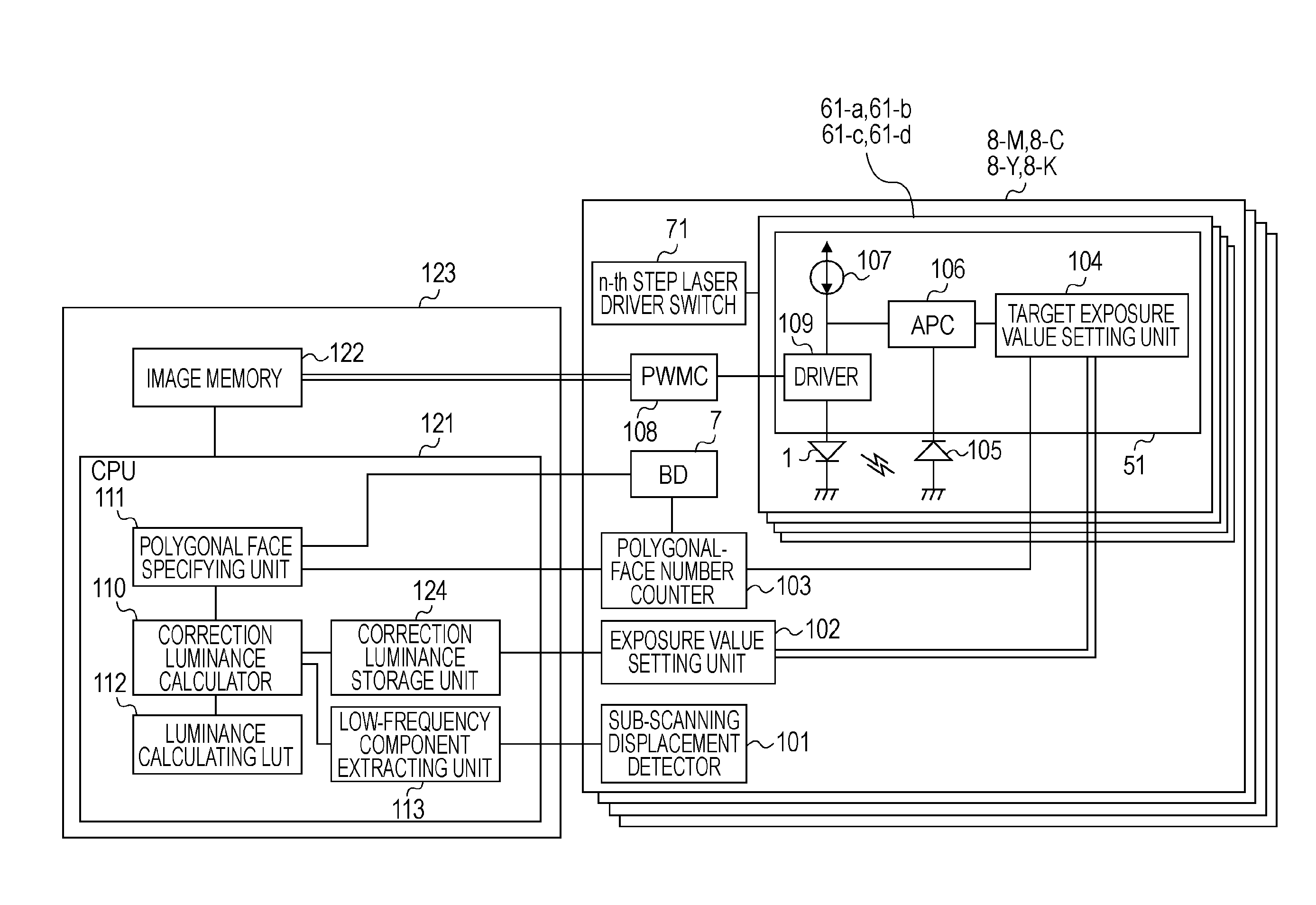
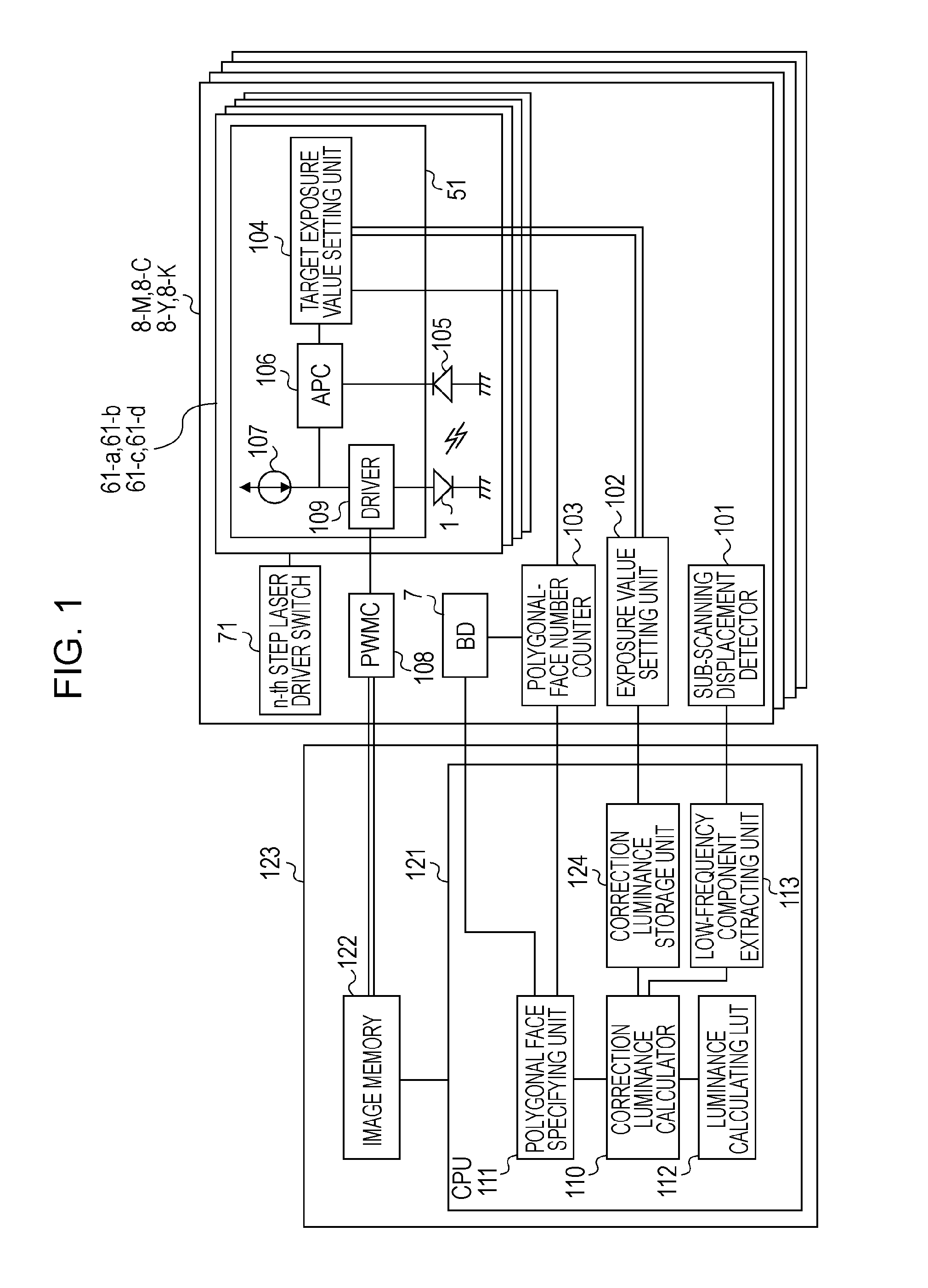
[0044]FIG. 1 is a block diagram of a printer according to an embodiment that forms images on an image bearing member by deflecting multi-laser beams with a rotatable polygonal mirror and that is capable of suppressing the unevenness of color density due to exposure amount changes in a sub-scanning direction. These blocks are connected together on conditions capable of reading and writing information with each other.

[0045]A printer engine controller 123 feeds data produced by a controller (not shown) to an exposure unit 8 with predetermined timing based on an image memory for printing images by drawing them with laser. Referring to FIG. 1, a CPU 121 in the engine controller 123 controls inside the engine, including the exposing timing control, the paper feed control (not shown), the conveying drive control (not shown), the high-voltage control (not shown), and the fixing control (not shown).

[0046]The exposure amount refers to a time-integrated value of laser irradiation on an exposed...

second embodiment

[0095]According to the embodiment described above, the 4-line moving averaged total exposure amount is maintained substantially constant, while the luminance is variable for each face (the luminance of 4 beams within one face is the same). According to a second embodiment, the 4-line moving averaged total exposure amount is maintained substantially constant, while the luminance is variable for each face and the luminance of 4 beams is variable.

(Effect of Example when Exposure Correction Resolution is Deteriorated)

[0096]FIG. 14A shows an example of the luminance correction value (luminance information) according to the second embodiment in which the luminance information is stored for each face and for each beam of the multi-laser beams. FIG. 14B is a drawing showing exposure amount correction situations according to the second embodiment. As shown in FIG. 14A, the resolution of an individual beam is deteriorated in decrements of 0.01 and the luminance is changed for each face and fo...

third embodiment

[0097]According to the embodiments described above, the exposure amount is averaged by a simple moving average method with a plurality of lines. Whereas, according to a third embodiment, characteristics of an FIR digital low-pass filter are assimilated to the human visibility.

[0098]FIG. 15A is a schematic image drawing of output images depicted with a laser optical system according to the third embodiment (5-face polygon, 6 beams for simultaneous writing, the resolution 1200 dpi, and the spot diameter 50 μm). FIG. 15B is a table of the sub-scanning displacement amount from the regular position generated due to the polygonal axis tangle, the polygonal face tangle, and the positional displacement of a plurality of laser beams, listed for each polygonal face and for each beam.

[0099]Namely, the concentration difference unevenness is generated with a 30-line period which is the product of the number of polygonal faces and the number of beams for simultaneous writing. FIG. 15C is a table ...


PUM


Abstract

For suppressing color density unevenness due to a polygonal face tangle, laser luminance is controlled so as to maintain the color density unevenness with a spatial frequency sensitive to human visibility substantially constant.

Description

BACKGROUND OF THE INVENTION[0001]1. Field of the Invention[0002]The present invention relates to an electrophotographic image forming apparatus having a deflection scanning exposure unit such as a polygonal mirror for deflecting light.[0003]2. Description of the Related Art[0004]In the field of electrophotographic image forming apparatuses, a tandem type image forming apparatus has been known having a plurality of image forming sections, in which different color images are sequentially transferred on a recording material held on a conveying belt for speeding up.[0005]FIGS. 21A and 21B show an example of the tandem-type color image forming apparatus. FIG. 21A is a general schematic view. This color image forming apparatus includes a transfer material cassette (not shown) mounted on the body bottom. The transfer materials placed on the transfer material cassette are taken one by one and supplied to the image forming section. In the image forming section, a transfer conveying belt 10 i...

Claims


Application Information

Patent Timeline
IPC IPC(8): G03G15/043
CPCG03G15/326G03G15/0435G03G2215/0404
Inventor TOMINAGA, HIDEKAZU
Owner CANON KK
Why Eureka
Try Eureka