
Medical device

a technology of medical devices and stents, applied in the field of medical devices, can solve the problems of large restrictions on the size or the like of the apparatus, the inability to accurately and certain the foramen ovale valve of a thin wall thickness, and the inability to accurately and certain the procedure of inosculating, etc., to achieve the effect of more speed, more accurate and certain the procedure, and the effect of speed

Active Publication Date: 2009-01-01
TERUMO KK
View PDF84 Cites 4 Cited by
  • Summary
  • Abstract
  • Description
  • Claims
  • Application Information

AI Technical Summary

Benefits of technology

[0012]The object of the present invention is to eliminate the problem mentioned above and provides a medical device in which it is hard for the thrombus to be attached to the electrode even if the electric energy is applied in the blood and it is possible to perform a procedure for fusing or necrosing the tissue safely and certainly.

Problems solved by technology

In particular, when a thrombus is attached on a disk-shaped membrane or the like on the left atrium side, this flows and there is a possibility that it becomes a cause of a stroke, and there is also a fear that a foramen ovale valve of a thin wall thickness is broken.
In addition, these members are not position-fixed in a state of being sandwiched and there is also a possibility of causing a positional displacement.
However, the foramen ovale, the foramen ovale valve and the atrial septum are different not only in small / large sizes but also in a condition of thicknesses, shapes or the like depending on persons and according to circumstances, it happens that the size or the like of the apparatus is restricted a lot.
Also, even on an occasion when the procedure is performed, there is a fear that it becomes difficult to pull various forms of foramen ovale valves to the foramen ovale at anytime and certainly.
When the biological tissue is thermally contracted, there is also a fear that the proximal side of the electrode member contacting with the biological tissue is exposed and a thrombus will attach on this exposed portion.

Method used


Image

  • Medical device
  • Medical device
  • Medical device

Examples


first embodiment

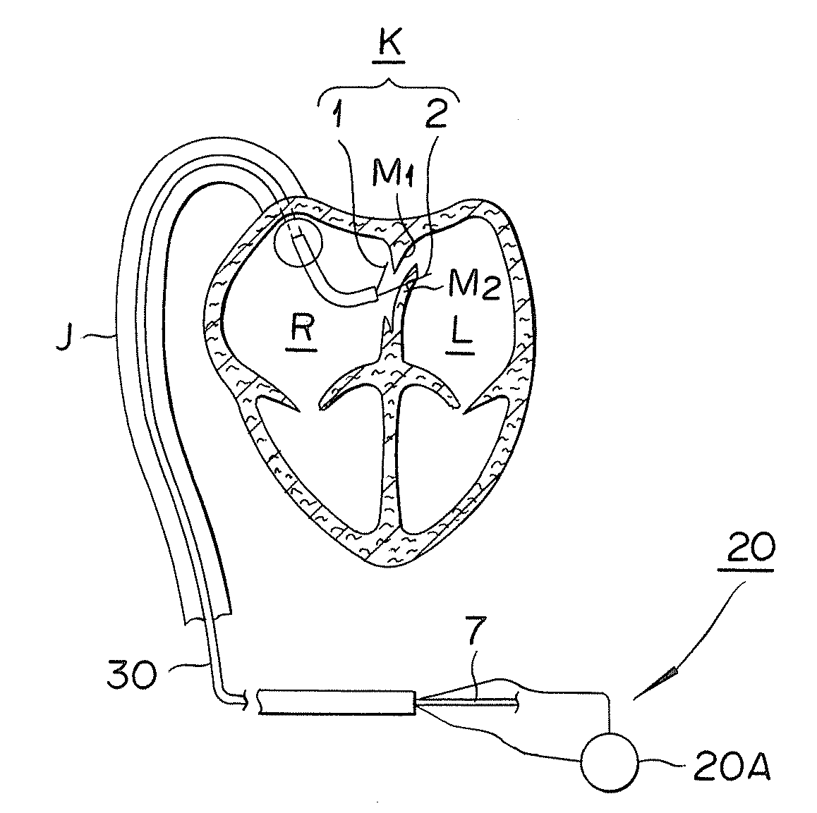
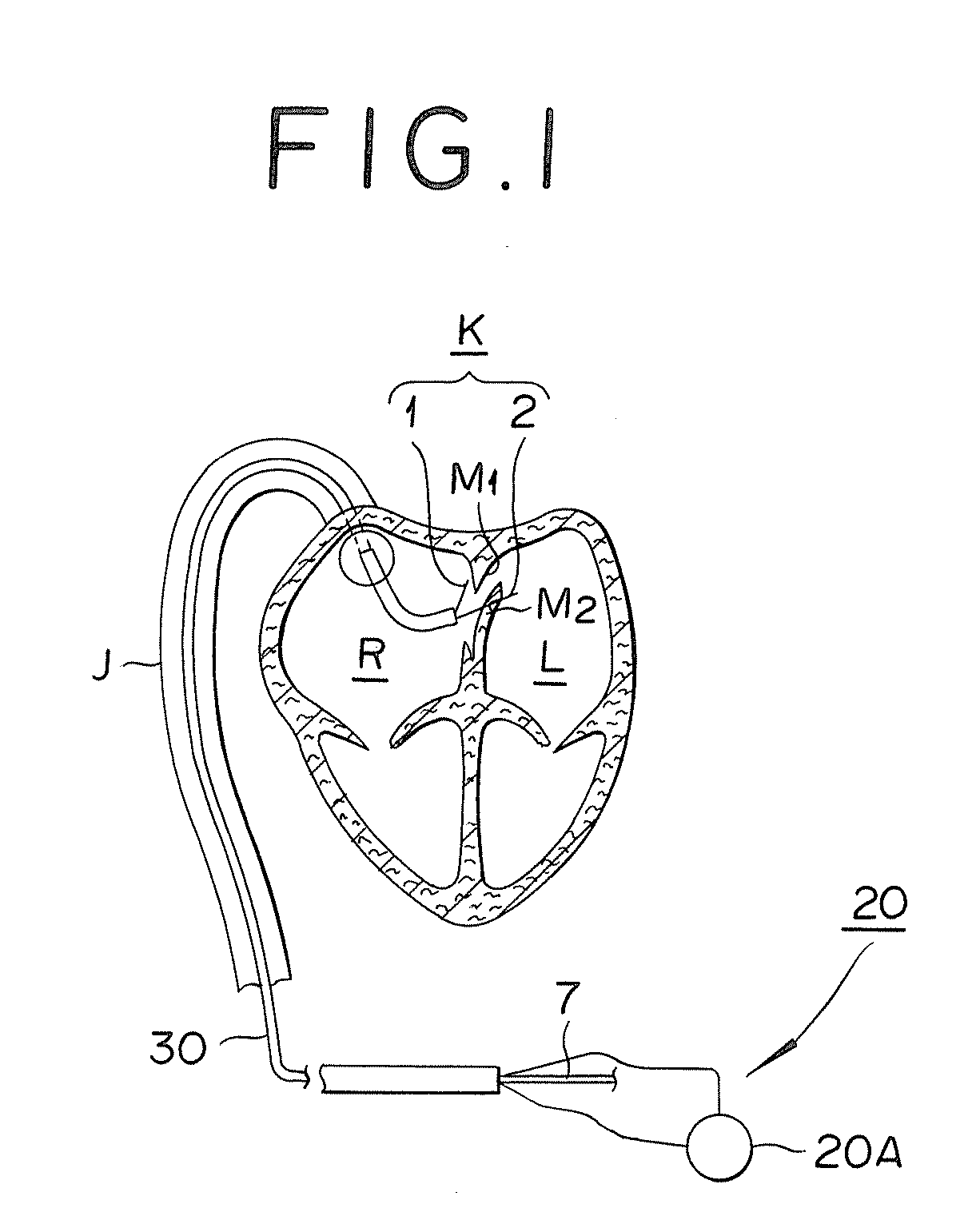
[0045]First, it is outlined with respect to a medical device for PFO of the First embodiment. This medical device, as shown in FIG. 1, includes a clamper K (first electrode member 1 and second electrode member 2) which is installed in a percutaneous catheter 30, and in a state of sandwiching a foramen ovale valve M2 and an atrial septum M1 which are biological tissues M by means of the clamper K, electric energy from an energy supply unit 20 is supplied to the sandwiched foramen ovale valve M2 and atrial septum M1, wherein both of them are to be inosculated or fused.

[0046]It should be noted in the drawing that J denotes an inferior vena cave, “L” denotes a left atrium and R denotes a right atrium.

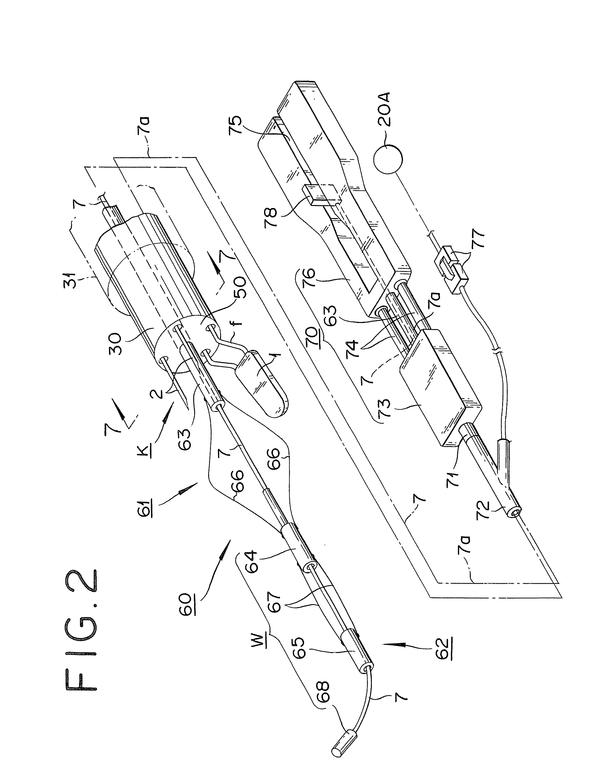
[0047]Specifically, the medical device is constituted as shown in FIG. 2. It should be noted in FIG. 2 that only an operation unit at hand 70 is demagnified because of space limitations.

[0048]The medical device includes an operation unit at hand 70 provided on the proximal side; a guiding c...

second embodiment

[0113]FIG. 10 is a cross-section view showing a clamper according to a second exemplified embodiment of the invention, FIG. 11A is a cross-section view along a 11-11 line of the FIG. 10, FIG. 11B is a cross-section view showing a modified example of the second electrode member and FIG. 12 is a cross-section view along a 12-12 line of the FIG. 10. It should be noted in the drawings that the same numerals are given to the same ones as the constitution members for the first exemplified embodiment.

[0114]As a third countermeasure for preventing a problem that a thrombus will be attached to the electrode member, it is also allowed to not transfer joule-heat of an electrode portion in the time of the electric energy supply to the side that a biological tissue does not contact.

[0115]The second electrode member 2 of the first exemplified embodiment is composed of a portion thereof which is protruded from a support body 50 of an attachment portion is a circular-shaped in the section perpendic...


PUM


Abstract

A medical device for fusing or necrosing a biological tissue, including a first electrode member and a second electrode member protruded from a non-electrically-conductive attachment portion configured to sandwich the biological tissue; and an energy supply unit configured to supply electric energy to between the first electrode member and the second electrode member, wherein the region of a predetermined length in a direction of axial line from the attachment portion in at least one of the electrode members within the first electrode member and the second electrode member is coated with an electrical insulator.

Description

CROSS-REFERENCES TO RELATED APPLICATIONS[0001]This application is based upon Japanese Patent Applications No. 2007-166773 and No. 2007-166792 filed Jun. 25, 2007 the contents of which are hereby incorporated by reference.BACKGROUND OF THE INVENTION[0002]1. Field of the Invention[0003]The present invention relates to a medical device which closes a defect occurring in a living body and particularly to an improvement of electrode members sandwiching a biological tissue.[0004]2. Description of the Related Art[0005]Recently, a patent foramen ovale (hereinafter, referred as to PFO: Patent Foramen Ovale) has been cited for a cardiogenic factor of a stroke and a hemi headache. A PFO is a symptom in which a foramen ovale which makes blood shunt for the right to the left in the heart of a fetal period remains even if a fetus becomes adult and it is said that 20 to 30% of adults possess it.[0006]The foramen ovale occurs at a septum secundum (Septum Secundum, hereinafter, referred to as atrial...

Claims


Application Information

Patent Timeline
Patent Type & Authority Applications(United States)
IPC IPC(8): A61B18/14
CPCA61B17/0057A61B18/1445A61B18/1477A61B2018/1497A61B2017/00575A61B2018/00083A61B2018/1425A61B18/1492
Inventor OOTSUBO, SEIICHI
Owner TERUMO KK
Learn More