Manipulator unit

Inactive Publication Date: 2009-01-01
ORBITAL ROBOTICS
View PDF10 Cites 12 Cited by
  • Summary
  • Abstract
  • Description
  • Claims
  • Application Information

AI Technical Summary

Benefits of technology

[0026]For this purpose, said system may further be provided with an encoder adapted to alert the controller of any such slippage and indicate the controller to tak

Problems solved by technology

Although most such a cut-away/weld is easily and accurately performed on a 3D model of the pipe on a computer, performing a desired cut-away/weld in reality tends to p

Method used


Image

  • Manipulator unit
  • Manipulator unit
  • Manipulator unit

Examples


Embodiment Construction

[0050]Geometric Configuration

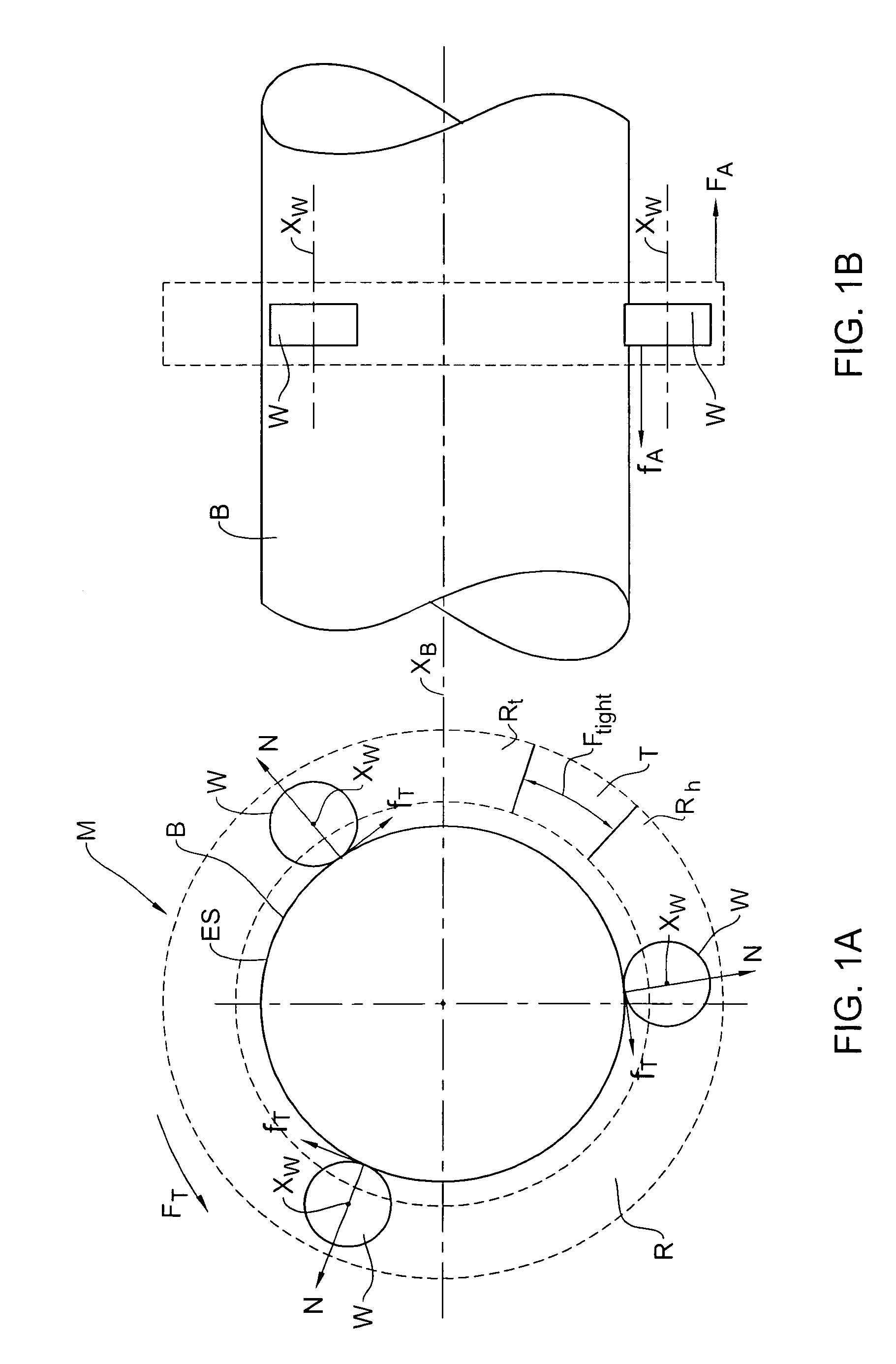
[0051]Turning to FIGS. 1A and 1B, a substantially cylindrical body generally designated B is shown having mounted thereon with a mechanism generally designated M comprising a ringed body R and three wheels W which are substantially equally angularly disposed, and are in contact with the external surface ES of the body B. The wheels W are arranges such that the axis of rotation thereof. XW is essentially parallel to the longitudinal axis XB of the body B. Uniform pressure is applied to the wheels W in a direction normal to the external surface ES so as to maintain contact with the external surface ES.

[0052]With particular reference to FIG. 1A, when rotating the mechanism M about the body B, a tangential force FT is required to overcome tangential friction fT. The friction fT may be calculated by parameters like N, the normal force applied on the external surface ES by the wheels W and μ, the friction coefficient between the wheels W and the external surfa...


PUM


Abstract

A manipulator add-on unit adapted for connection to a system designed for performing operations on a body having a central axis and a surface extending about said central axis, when mounted onto said surface and further adapted for performing rotary motion about said central axis, said manipulator add-on unit comprising a housing with a drive assembly, and a manipulator arm having a longitudinal axis and articulated to said drive assembly, wherein said housing is adapted for mounting onto said system, and said drive assembly is adapted for providing said manipulator arm with at least a reciprocal axial movement in the direction of said longitudinal axis.

Description

FIELD OF THE INVENTION[0001]This invention relates to pipe-work machinery, in particular, for marking, cutting, welding of pipes etc.BACKGROUND OF THE INVENTION[0002]Pipes are generally hollow tubular bodies generally having a central axis about which the body of the pipe is disposed, defining an axial direction thereof. Pipes are employed in a wide variety of fields and implementations such as water and sewage infrastructure, irrigation, industrial plants etc.[0003]There is always a need to cut away or weld portions of the pipe for various purposes such as joining an additional pipe thereto (in alignment or in intersecting relation therewith), creating an opening for removal of material from the pipe etc.[0004]The cut-away / weld may be of various geometric shapes ranging from straight cutting of the pipe perpendicular to the central axis thereof, to elaborate shapes such as for transition bodies, connecting of pipes of different shapes and sized etc.[0005]Although most such a cut-aw...

Claims


Application Information

Patent Timeline
IPC IPC(8): B25J13/00
CPCB08B9/023B08B9/045B08B9/049Y10T74/20207B23K37/0258B25J9/065B25J18/00B23K37/0217
Inventor KRONENBERG, AMI
Owner ORBITAL ROBOTICS
Why Eureka
Try Eureka