

Storage system and control method of storage system
a storage system and control method technology, applied in the field of storage system and control method of storage system, can solve the problems of data stored in the cache memory being overwritten and lost, normal components such as the cache memory, the host interface or the disk interface being subject to unauthorized access, etc., to prevent the loss of user data, high reliability, and high availability
- Summary
- Abstract
- Description
- Claims
- Application Information
AI Technical Summary
Benefits of technology
Problems solved by technology
Method used
Image

Examples
first embodiment
[0068][First Embodiment]
[0069]This embodiment explains a storage system with superior tolerance for fault. Specifically, the storage system of this embodiment has a function which cuts off the I / O path of the controller when an error occurs in any component or component in a controller, specifies the failed component in the cut-off status, and invalidates the failed component. In addition, after invalidating the failed component, the storage system of this embodiment determines whether the storage system itself is operable only with the normal components (i.e., the non-failed components), cancels (releases) the cutoff of the I / O path when operable, and resumes operation by rebooting the controller. The cutoff / release of the I / O path of the controller is conducted by the switch LSI mediates the controller and other units based on an error detection signal.
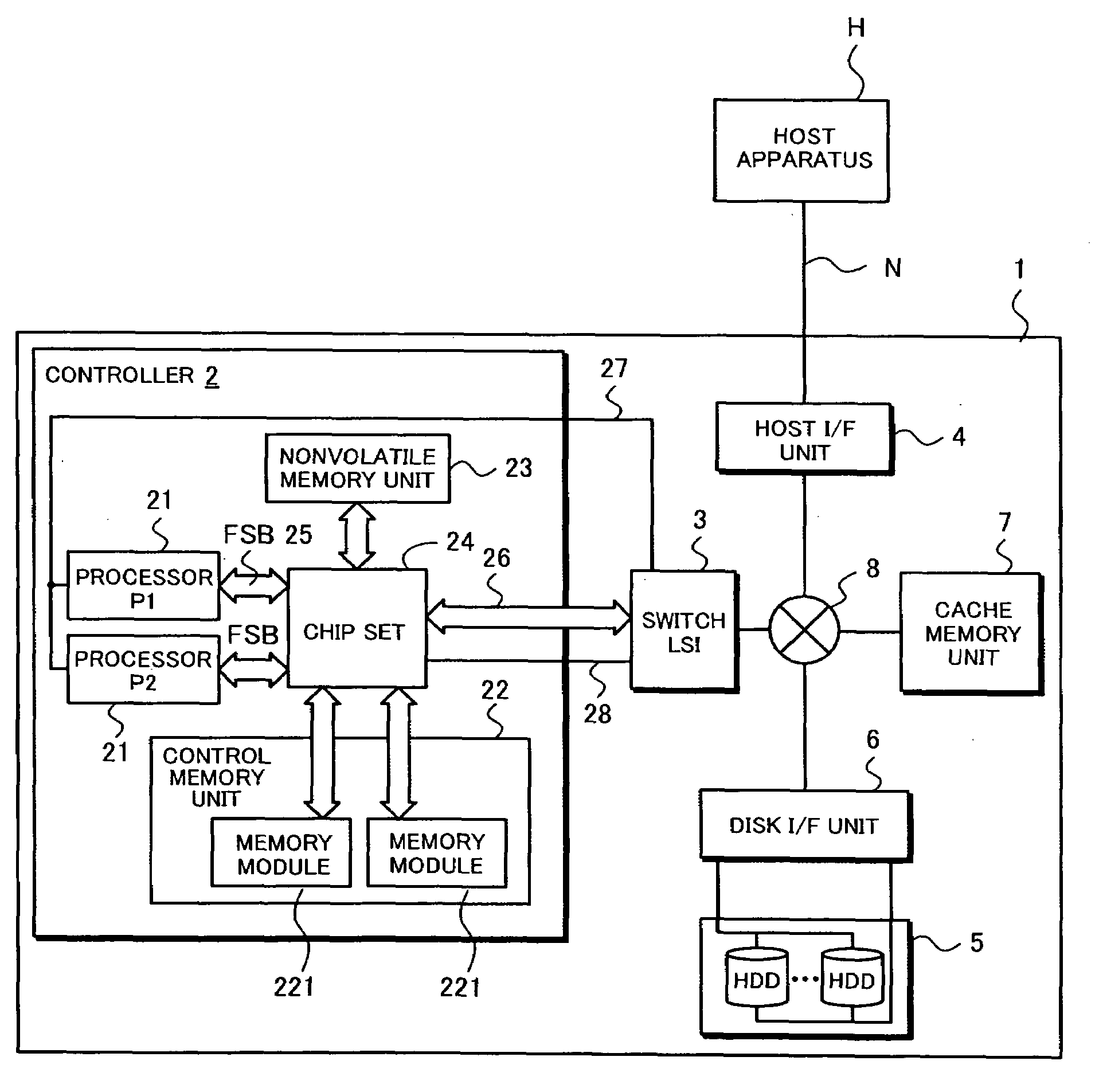
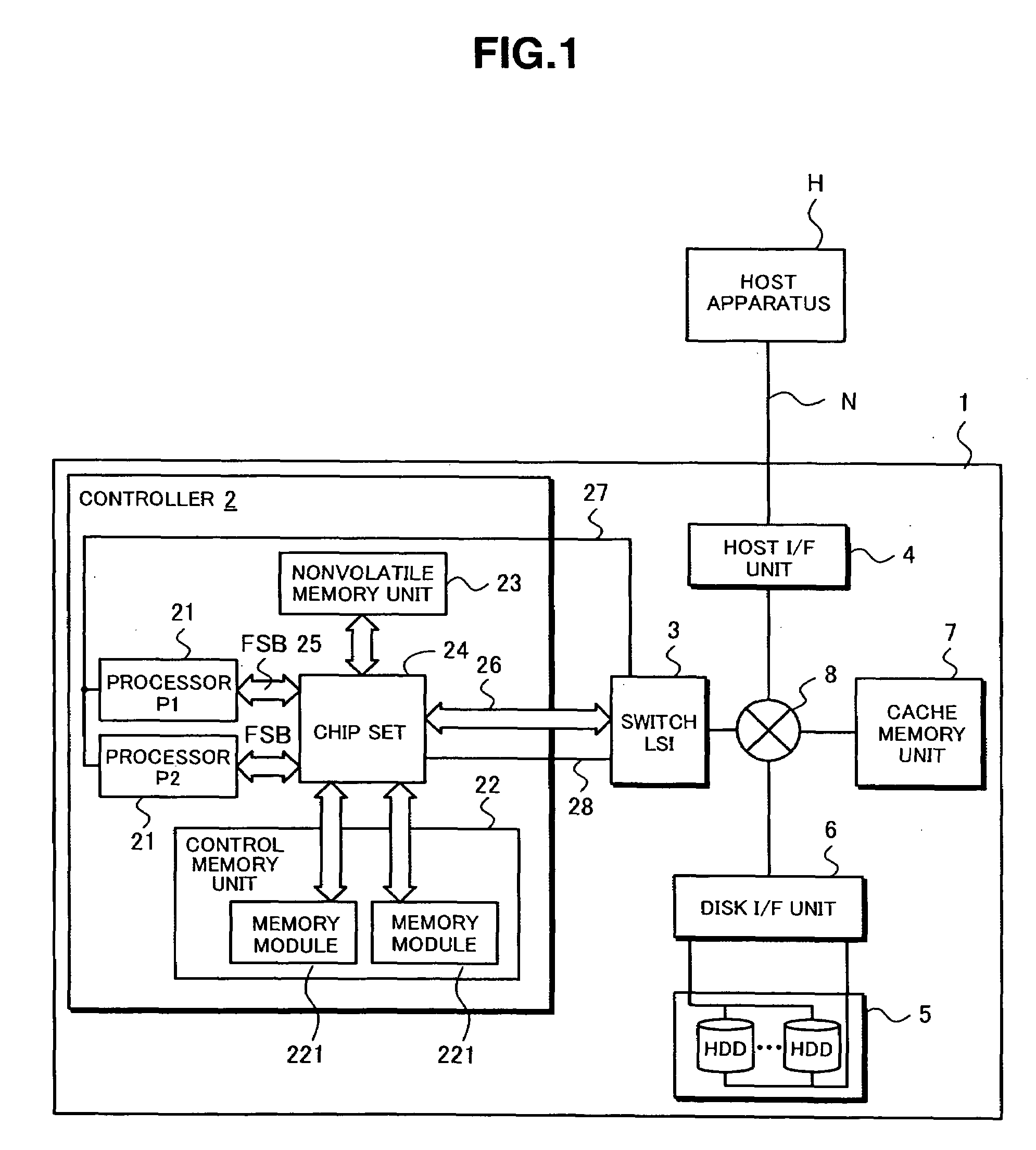
[0070]FIG. 1 is a diagram showing a configuration of a storage system 1 according to an embodiment of the present invention. Refer...
second embodiment
[0153][Second Embodiment]
[0154]The foregoing embodiment explained the error handling in a case where an error has occurred in any one of the components (components) in the controller 2. In this embodiment, a case is explained where an error has occurred in another unit in the storage system 1; for instance, in the cache memory unit 16.
[0155]FIG. 21 is a diagram showing the configuration of the cache memory unit 7 according to an embodiment of the present invention. As shown in FIG. 21, the cache memory unit 7 comprises a memory controller 71, and a plurality of memory modules 72. The memory controller 71 receives an access request from another unit in the storage system 1, and performs control for accessing the appropriate memory module 162.
[0156]The memory controller 71 and the plurality of memory modules 72 are connected with the memory bus 73 and the control signal line 74. The memory bus 73 is used as the address and for transferring data to enable the memory controller 71 to ac...
third embodiment
[0181][Third Embodiment]
[0182]This embodiment the failover / failback mechanism of the controller 2 having a mirrored configuration. Specifically, this embodiment explains the mechanism where, when a error occurs in the one of the controllers 2, another controller 2 takes over the processing during the error handling of such failed controller 2, and the processing taken over by the other controller 2 is returned to the controller 2 when the error handling is complete.
[0183]FIG. 27 is a diagram showing the configuration of the storage system 1 according to an embodiment of the present invention. The storage system 1 shown in FIG. 27 is adopting a mirrored configuration, and, therefore, the controller 2, the switch LSI 3, the host interface (I / F) unit 4, the disk interface (I / F) unit 6, and the cache memory unit 7 are respectively provided in a plurality.
[0184]The basic configuration of the controller 2 in this embodiment is the same as the foregoing embodiment. However, since a mirrore...
PUM
 Abstract
Description
Claims
Application Information