Exhaust manifold having improved NVH characteristics

a technology of exhaust manifold and nvh, which is applied in the direction of mechanical equipment, machines/engines, other domestic objects, etc., can solve the problems of reducing the fuel efficiency of the vehicle, affecting the performance of the exhaust manifold, so as to improve the exhaust manifold and reduce the nvh

Inactive Publication Date: 2009-01-08
METALDYNE TUBULAR COMPONENTS
View PDF6 Cites 13 Cited by
  • Summary
  • Abstract
  • Description
  • Claims
  • Application Information

AI Technical Summary

Benefits of technology

[0009]An exhaust manifold assembly is provided. The exhaust manifold assembly may consist of an upper half shell secured to a lower half shell to form a housing. The upper half shell and / or the lower half shell may have one or more tubes extending within the interior of the housing. An inlet flange and an outlet flange may be attached to one of the shells. The inlet flange may be attached to a cylinder head to receive exhaust gases from the cylinder head. The exhaust gases may be received by the one or more tubes. Advantageously, the improved exhaust manifold assembly may reduce NVH.

Problems solved by technology

However, these manifolds are heavy, cumbersome, and therefore detract from the fuel efficiency of the vehicle.
In addition, the cast iron manifolds are difficult to manufacture into compact shapes and other distinct shapes as may be required by the underhood packaging constraints of modern vehicles.
However, these sheet metal manifolds present several disadvantages.
In particular, since the sheet metal manifolds are thin and lighter in weight, the sheet metal manifolds provide noise, vibration, and harshness (“NVH”) problems.
For example, the NVH problems present objectionable noise and vibration from the exhaust pulses.
Furthermore, the sharing of exhaust pulses among cylinders via the exhaust manifold (i.e. “cross-talk”) may compound the NVH problems and may result in further objectionable noise and vibration.
The NVH transmitted and experienced by the passengers is bothersome and undesirable.

Method used


Image

  • Exhaust manifold having improved NVH characteristics
  • Exhaust manifold having improved NVH characteristics

Examples


Embodiment Construction

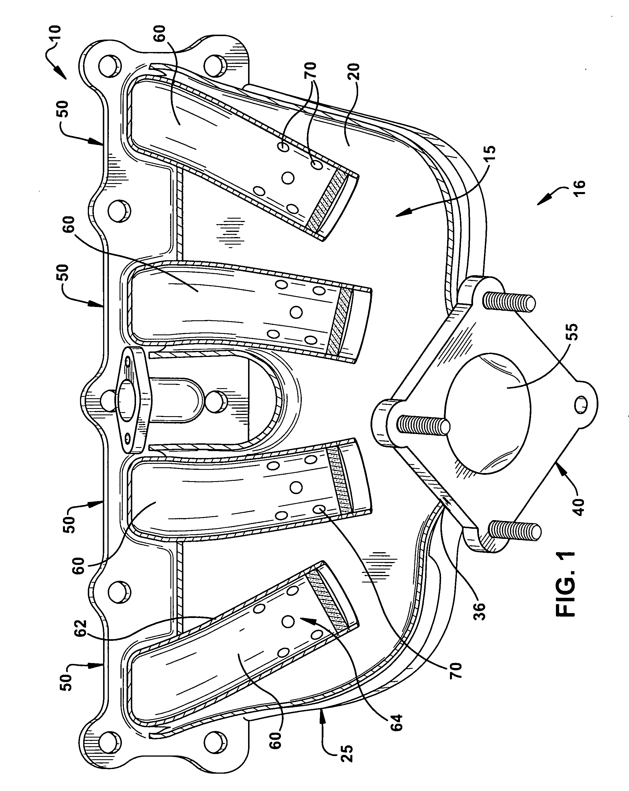
[0012]Referring now to FIG. 1, an exhaust manifold 10 is illustrated. The manifold 10 may include a lower half shell 20 and an upper half shell (not shown). The lower half shell 20 and the upper half shell may be integrally formed, attached, such as by welding or fastening, or otherwise joined together. The upper half shell and the lower half shell 20 may be joined to define a housing 25.

[0013]The housing 25 may be defined between the upper half shell and the lower half shell 20. The housing 25 may have an outlet flange 40 providing fluid communication between an interior 15 of the housing 25 and an exterior 16 of the housing 25. The outlet flange 40 may have an opening 55 permitting fluid communication between the remainder of the exhaust system and the housing 25. The outlet flange 40 may be sized and shaped for attachment to a remaining portion of the exhaust system (e.g. exhaust piping, turbocharger, etc.). The outlet flange 40 may be connected to the housing 25, such as to the ...


PUM

PropertyMeasurementUnit
distanceaaaaaaaaaa
lengthaaaaaaaaaa
strengthaaaaaaaaaa

Abstract

An exhaust manifold and method of manufacturing the same is provided that includes at least one tube within shells of an exhaust manifold. The tube limits fluid communication from the tube into the shells of the exhaust manifold. An inlet flange is connectable to the exhaust manifold and is attachable to a cylinder head of a combustion engine. Exhaust gases expelled from the cylinder head are transmitted into the exhaust manifold. At least a portion of the exhaust gases pass through the tube. The exhaust manifold reduces NVH and cures emission control issues.

Description

CROSS-REFERENCE TO RELATED APPLICATIONS[0001]This application claims benefit from U.S. Provisional Patent Application No. 60 / 934,376, entitled “Exhaust Manifold Having Improved NVH Characteristics,” filed on Jun. 13, 2007, which is hereby incorporated in its entirety by reference.FIELD OF THE INVENTION[0002]This invention generally relates to an exhaust manifold that may be incorporated into an internal combustion engine, and more particularly to an exhaust manifold having exhaust tubes within an exhaust manifold housing that may improve noise, vibration and harness characteristics of the manifold housing.BACKGROUND[0003]In an internal combustion engine, a cylinder head is positioned atop an engine block having cylinders (or combustion chambers) extending therethrough. Upper portions of each combustion chamber extend through the cylinder head, where the upper portion of each combustion chamber corresponds with each cylinder of the engine block. The cylinder head may also house intak...

Claims


Application Information

Patent Timeline
Patent Type & Authority Applications(United States)
IPC IPC(8): F01N7/10B21D51/16F01N13/10
CPCF01N13/10F01N13/1888Y10T29/49398F01N2470/02F01N2230/00
Inventor SCHMIDT, MICHAEL PAUL
Owner METALDYNE TUBULAR COMPONENTS
Why Eureka
Try Eureka