
Climate zone control

a technology of climate control and zone control, which is applied in the field of heating and cooling, can solve the problems of inability to achieve and maintain a desired and consistent temperature throughout the building, inability to use fossil fuels to create the energy needed by all heating and cooling systems, and overheating or cold rooms closest to air handlers, so as to save the user's money on heating and cooling costs and unnecessary energy consumption

Inactive Publication Date: 2009-01-08
ENERGY PLUS TECH
View PDF5 Cites 14 Cited by
  • Summary
  • Abstract
  • Description
  • Claims
  • Application Information

AI Technical Summary

Benefits of technology

[0007]This invention involves the heating and cooling of a building by dividing the building into separate climate zones. Each zone with its own thermostat can be set to a different temperature. This allows multiple occupants of a home or office to be comfortable at different temperatures at the same time. This invention conserves energy and protects valuable natural resources. This invention is designed to provide a simple cost effective solution for the problem of excess airflow, such as too much cold air when the air condition is on or too much hot air when the heat is on. Additionally, the system can regulate temperature when there is not enough airflow, such as providing more cold or hot air as needed. The system is easy to install and operate. The system can be used with an existing air conditioning system and no additional hardware or wiring is required. There are three components to the system: (1) a master thermostat, (2) a wireless remote thermostat and (3) wireless vents with remote controlled louvers. There is no computerized interface between the master thermostat and the air handler. The term “master thermostat” as used herein refers to the thermostat of the invention that has the ability to control the air handler and wirelessly control the vents within a designated zone which are set to be controlled by the master thermostat. The master thermostat of the invention also has the ability to receive signals from the wireless remote thermostats. The term “remote thermostat” as used in respect of the invention refers to a thermostat that controls a designated zone and wirelessly communicates with vents in the designated zone and also has the capability to wirelessly communicate with the master thermostat. The term “vents” as used in respect of the invention refers to vents capable of receiving wireless instruction from either a master thermostat or a remote thermostat and opening or closing the louvers of the vent. The term “wireless” as used in respect of the invention refers to wireless protocols including conventional radio frequency (RF), BLUETOOTH™, ZIGBEE™, WIFI™ and other suitable wireless protocols that are known or that may become available. Reference herein to an “existing thermostat” means a conventional thermostat that is preexisting in a standard heating and cooling system.
[0016]The climate control system is easy to implement with existing air conditioning and heating systems. No additional hardware or wiring is required other than the special vents and thermostats. The system is completely wireless. The communication between the remote thermostat and the master thermostat and the communication between the vents and the remote thermostat or the master thermostat is transmitted by a wireless signal. Each thermostat of the system communicates on its own channel. A unique channel of communication is established between each wireless thermostat and the vents in its designated zone by the use of dip switches, jumper switches, electronic logic or other similar mechanisms well known in the art for pairing wireless devices. The unique channels are set at the time of installation but can be changed as necessary. This unique channel prevents inadvertent opening or closing of vents by a remote thermostat in zones assigned to a different remote thermostat. In addition there is a separate wireless channel, set in similar fashion, for communication between the master thermostat and the remote thermostat(s). Accordingly, the system is extremely convenient to install, as no hardwiring of the system is required. Use of a remote thermostat allows every room or zone to have its own thermostat. The remote thermostat is battery operated and wireless and can be mounted or placed anywhere in the room. The remote thermostat has the ability to function independently in a single zone system allowing a user to control the excess airflow and thus temperature of the room by opening and closing the vent irrespective of the setting of the, existing thermostat. It can also be used in a multi zone system in conjunction with a master thermostat and vents.
[0019]The climate zone control allows a user to leave unoccupied areas without heating and cooling, saving the user money on heating and cooling costs and unnecessary consumption of energy. The vents regulate airflow and room temperature through a remote signal received from the zone's thermostat. A battery operated wireless thermostat is placed anywhere in the zone or room. The thermostat is set at a desired temperature. The vents will receive a signal from the wireless thermostat instructing the vents to open or close as needed.

Problems solved by technology

The price of fossil fuels which are used to create the energy needed by all heating and cooling systems are increasing rapidly.
The problem with the standard system is the inability of the system to attain and maintain a desired and consistent temperature throughout the building.
This can cause the rooms closest to the air handler to be overly hot or cold.
This also consumes a considerable amount of wasted energy.
Currently the most common way to accomplish this is to use a hard wired damper system which is a costly and an inefficient remedy.
Even with these modifications, it is very difficult to control or vary the temperature of one room.

Method used


Image

  • Climate zone control
  • Climate zone control
  • Climate zone control

Examples


Embodiment Construction

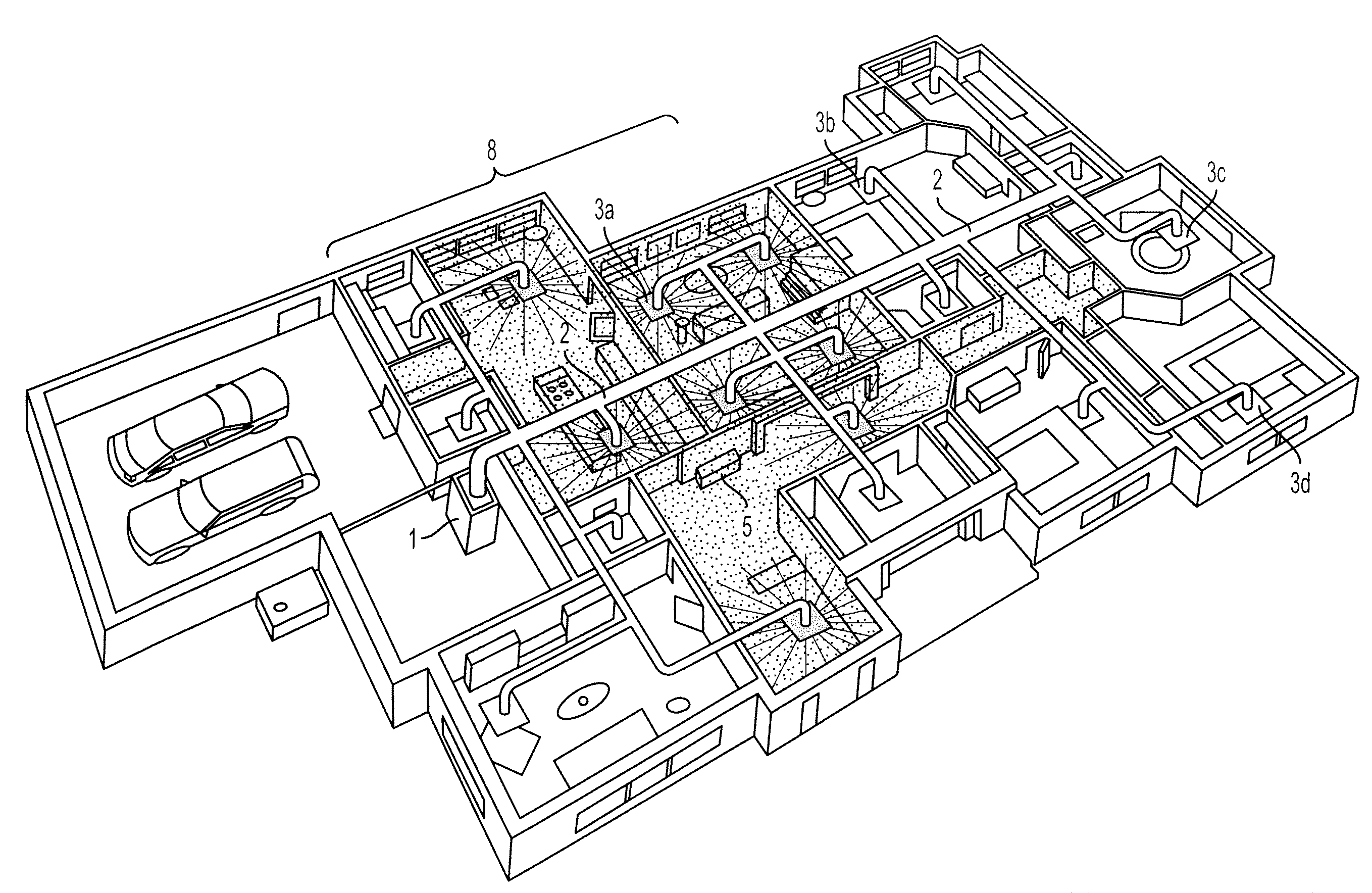
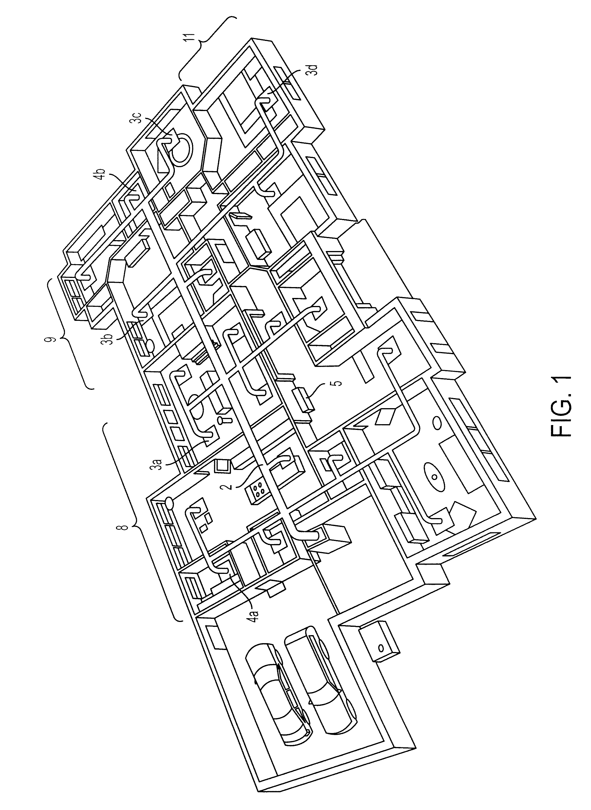
[0031]FIG. 1 is a perspective view of the system in a one story home as shown by way of a floor plan. The air handler 1 is connected to duct work 2 which carries the cooled or heated air to each room. The air enters the rooms by vents 3a, 3b, 3c and 3d. The master thermostat 5 allows a user to select a temperature and other settings of the air handler 1. The system, like all systems, may require discharge zones 4a and 4b to discharge excess air pressure when several vents shut simultaneously. The airflow system allows the home to be divided into separate climate zones 8, 9 and 11. Accordingly, the individuals in the home only use the air needed, when and where it is required.

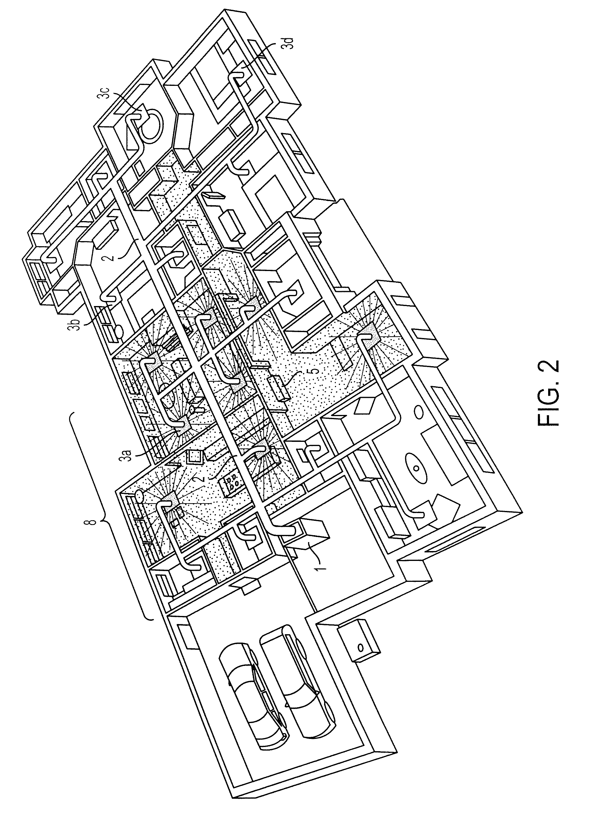
[0032]FIGS. 2, 3 and 4 demonstrate the airflow system by way of exemplary use of an embodiment of the system. As shown in FIG. 2, the individuals in the home can set the master thermostat 5 in zone 18 at 74°. The master thermostat then communicates to all the vents 3a in zone 18 as to whether the vents should be...


PUM


Abstract

The disclosed climate zone control system separates a building into separate climate zones, which allows a user to select the desired temperature of each zone. In a single zone, the climate zone controlling system controls the temperature of the single zone where an existing thermostat controls the temperature of air exiting an air handler and the remote thermostat controls the temperature of the designated zone of the building by controlling airflow from the vents. In a multiple zone system, there is a master thermostat that controls the air handler and multiple remote thermostats for multiple designated zones where the remote thermostat controls both the temperature and the airflow.

Description

PRIORITY[0001]This application is being filed as a nonprovisional patent application claiming priority to provisional application Ser. No. 60 / 897,986 under 35 U.S.C. § 119.FIELD OF INVENTION[0002]This invention involves the heating and cooling of a building by controlling the temperature of each room in a building, which conserves energy and protects natural resources. The climate in each zone is controlled by remote controlled wireless vents that open and close depending upon wireless signals received from a master thermostat or a remote thermostat located in the particular zone. In a single zone application, the remote thermostat controls the temperature of the single zone by controlling airflow whereas an existing thermostat controls the temperature of air exiting an air handler. In a multiple zone system, the existing thermostat is replaced by the master thermostat of the invention which performs all the functions of a conventional thermostat. The master thermostat has the abili...

Claims


Application Information

Patent Timeline
IPC IPC(8): G05D23/00F24F7/007F24F3/00G08B21/00
CPCF24F11/0009F24F2011/0068F24F2011/0067F24F11/0076F24F11/30F24F11/54F24F11/56F24F11/70F24F11/52F24F11/46F24F11/63
Inventor HOLLAND, JUDAH BENJAMINKAISER, STEWART RONALD
Owner ENERGY PLUS TECH
Learn More