Method for infrared imaging of living or non-living objects including terrains that are either natural or manmade

a technology of infrared imaging and living objects, applied in the field of infrared imaging of living or non-living objects including terrains, can solve the problems of limited depth of field (dof) of ir cameras, similar to standard optical systems, and limit the depth of field an observer can see in the image, so as to achieve the effect of improving the depth of field

Inactive Publication Date: 2009-01-08
NORTHROP GRUMMAN SYST CORP
View PDF11 Cites 24 Cited by
  • Summary
  • Abstract
  • Description
  • Claims
  • Application Information

AI Technical Summary

Benefits of technology

[0007]In one embodiment, a single IR camera may be used to capture multiple image of the same scene from a

Problems solved by technology

However, Depth of Field (DOF) in IR cameras is limited similar to standard o

Method used


Image

  • Method for infrared imaging of living or non-living objects including terrains that are either natural or manmade
  • Method for infrared imaging of living or non-living objects including terrains that are either natural or manmade
  • Method for infrared imaging of living or non-living objects including terrains that are either natural or manmade

Examples


Embodiment Construction

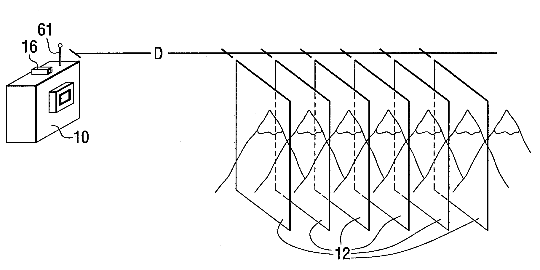
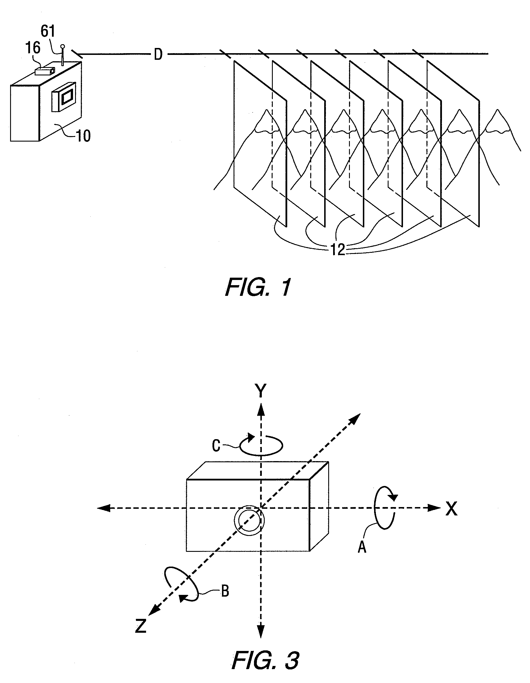
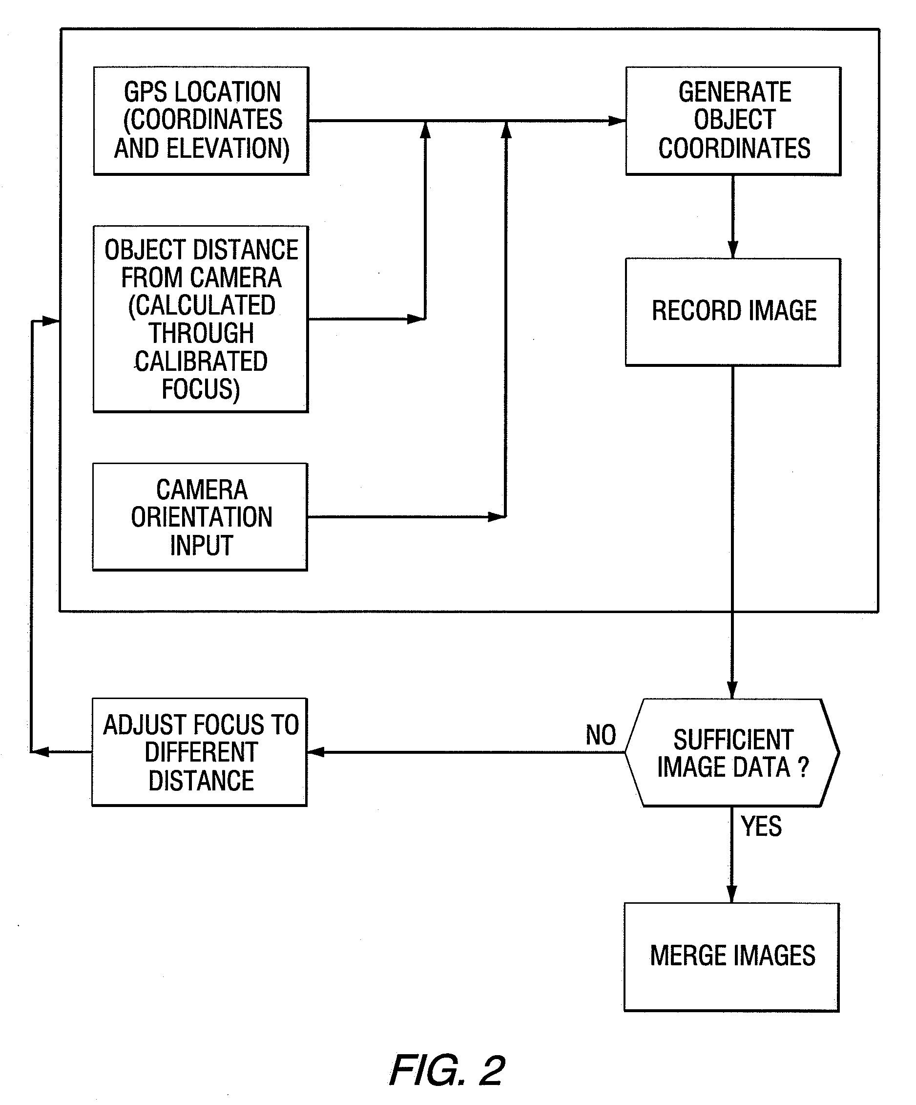
[0020]Infrared cameras convert IR radiation (˜750 nm to 1 mm) to a digital signal based on the wavelength of the radiation. As the makeup of terrain changes so too does the IR radiation produced by the surface. IR cameras are able to detect these changes and portray them as an image. Focal planes 12 are described and visualized as two dimensional as shown in FIG. 1. As commonly used, the term “focal plane” refers to planes, perpendicular to the optic axis, which pass through the front and rear focus points behind the lens of the camera. As used herein the term “focal plane” refers to a plane, perpendicular to the optic axis, which passes through the front focus point, i.e. a plane within the object space unless expressly indicated to have a different meaning. The term “optic axis” refers to an imaginary line perpendicular to the lens of a camera and passing through the center of the lens. As used herein the term “image” refers to a visual representation of an object or scene which m...


PUM


Abstract

An improved system for infrared (IR) imaging of terrain is disclosed wherein or or more IR cameras may be used at one or more locations to record images at multiple focal planes. The images are all taken of the same field of view but at varied focal planes. Global Positioning Satellite (GPS) may be used to track each camera location and each camera captures images of the object. Information regarding the orientation of the camera may also be measured. The digital information from the images from each camera at varying focal planes, the distance from the object to each camera, orientation of camera and the GPS location of each camera is transferred to a computer where the data is processed through the use of merging and photogrammetry software utilizing appropriate algorithms to convert the multiple images into a two-dimensional or three-dimensional image with improved depth of field.

Description

CROSS REFERENCE TO RELATED APPLICATIONS[0001]This application is a continuation-in-part of U.S. patent application Ser. No. 11 / 742,751 filed May 1, 2007, which is a continuation-in-part of U.S. patent application Ser. No. 11 / 506,701 filed Aug. 18, 2006, which is a continuation-in-part of U.S. patent application Ser. No. 10 / 971,217 filed Oct. 22, 2004, both of which are herein incorporated by reference.GOVERNMENT CONTRACT[0002]United States Government has certain rights to this invention pursuant to the funding and / or contracts awarded by the Strategic Environmental Research and Development Program (SERDP) in accordance with the Pollution Prevention Project WP-0407. SERDP is a congressionally mandated Department of Defense (DOD), Department of Energy (DOE) and Environmental Protection Agency (EPA) program that develops and promotes innovative, cost-effective technologies.FIELD OF THE INVENTION[0003]The present invention relates to improved infrared imaging of living or non-living obj...

Claims


Application Information

Patent Timeline
IPC IPC(8): G01J5/00H04N13/239
CPCG06T7/0022H04N13/0239H04N5/33H04N5/23232H04N13/239H04N23/951
Inventor WEIR, JOHN DOUGLASCHRIST, ROBERT JOHNFONNELAND, NILS JAKOB
Owner NORTHROP GRUMMAN SYST CORP
Why Eureka
Try Eureka