Three-Dimensional Image Forming System

a three-dimensional image and forming system technology, applied in the field of three-dimensional image forming system, can solve the problems of inability to confirm a three-dimensional image, inability to accurately convey the actual stereoscopic image, and easy damage to fine lenticular lenses, and achieve excellent economic efficiency and simple structure.

Inactive Publication Date: 2009-01-08
SHARP KK
View PDF15 Cites 26 Cited by
  • Summary
  • Abstract
  • Description
  • Claims
  • Application Information

AI Technical Summary

Benefits of technology

[0034]The three-dimensional image forming system according to the present invention has a simple structure with an excellent economic efficiency and can easily and economically form a three-dimensional image in line with a stereoscopic image recognized by a person's eyes.

Problems solved by technology

Therefore, there is a concern that the information of an actual stereoscopic image is not accurately conveyed.
However, it is not possible to confirm a three-dimensional image, which is formed based on the obtained three-dimensional image information, at the site where the image was captured.
As such, the problem with this apparatus is that it requires a separate display apparatus, printer or the like to confirm the three-dimensional image obtained.
The fine lenticular lens is extremely easy to sustain damage, and further an optical effect thereof is significantly affected by the damage.
Accordingly, manufacturing a printer capable of obtaining a three-dimensional image with a predetermined level requires a low mass productivity and a strict management level.
Further, forming a lenticular lens which is a fine optical device in a sheet requires a high precision die, which is difficult to manage, and a manufacturing line, which has a high degree of cleanness.
This results in a problem of impairing the economic efficiency.
Further, Reference 4 requires printing not only the image information but also a parallax barrier, thus requiring an apparatus having a complex structure, which also results in impairing the economic efficiency.
Accordingly, there is a concern that the three-dimensional image on a three-dimensional image print obtained by the printer may be significantly different from the stereoscopic image actually recognized by eyes.
As a result, there is a concern that a user may not be able to assuredly obtain a desired three-dimensional image.

Method used


Image

  • Three-Dimensional Image Forming System
  • Three-Dimensional Image Forming System
  • Three-Dimensional Image Forming System

Examples


Embodiment Construction

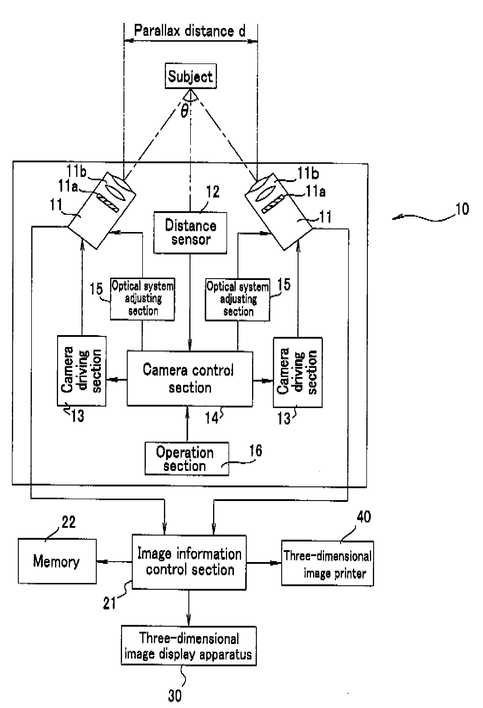
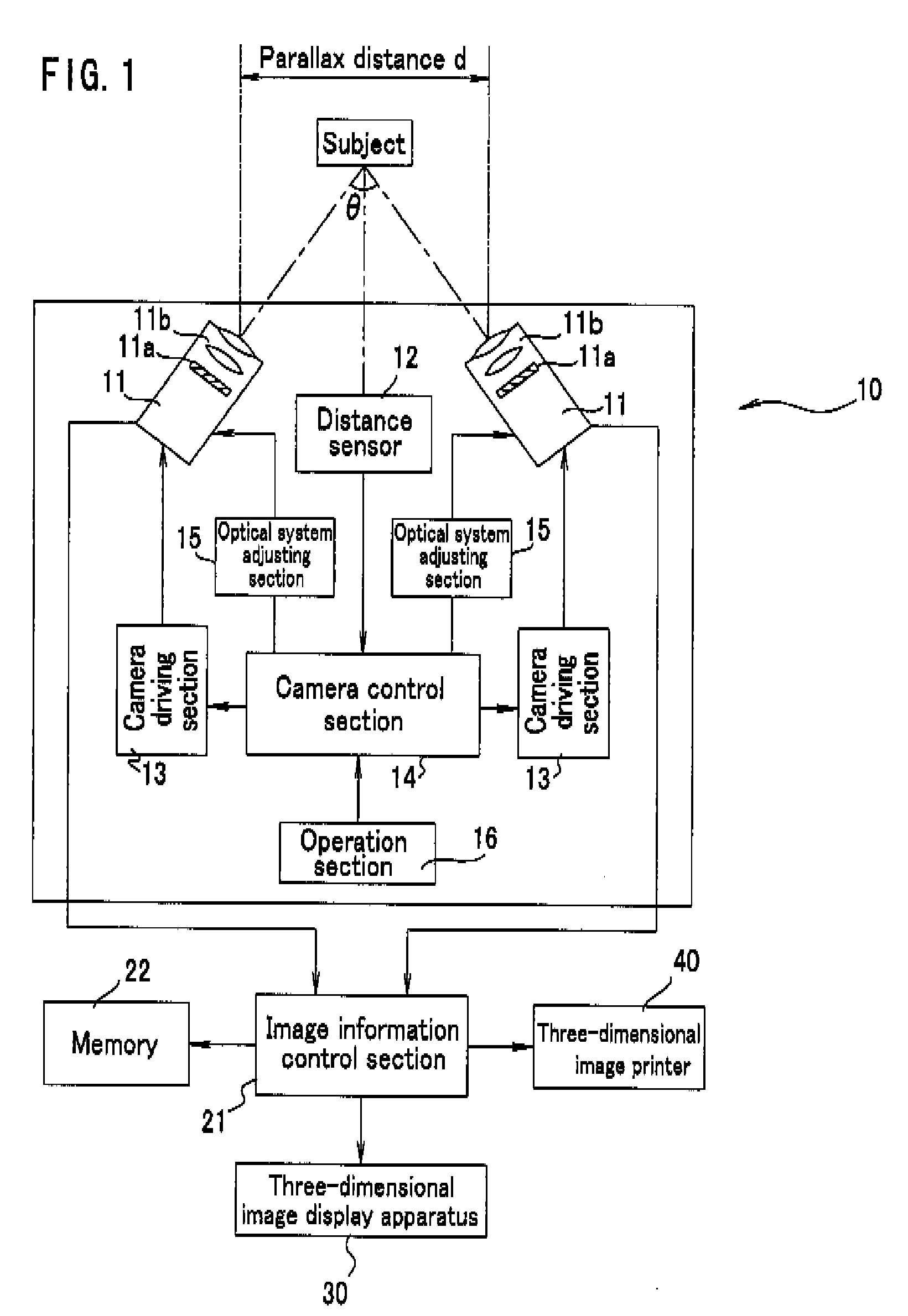
[0044]FIG. 1 is a block diagram schematically showing a structure of a three-dimensional image forming system according to the present invention. This three-dimensional image forming system includes: a three-dimensional image information obtaining apparatus 10 for obtaining three-dimensional image information of a subject; an image information control section 21 for performing a predetermined image process on the three-dimensional image information supplied thereto, which is obtained by the three-dimensional image information obtaining apparatus 10; a three-dimensional image display apparatus 30 for displaying a three-dimensional image based on the image information obtained as a result of the image-processing performed by the image information control section 21; a three-dimensional image printer 40 for printing the three-dimensional image on a recording paper, based on the image information provided from the image information control section 21; and a memory 22 as storage means fo...


PUM


Abstract

Information for each of a right eye and a left eye obtained by a pair of cameras, which is provided on a three-dimensional image information obtaining apparatus, is displayed on a three-dimensional image display apparatus. An optical axis of each of the cameras is disposed so as to intersect each other on a horizontal surface or on a surface inclined with respect to the horizontal surface. Based on a detection result of a distance sensor for detecting a distance between each of the cameras and a subject, an image capturing position of each of the cameras is adjusted such that the intersection point of the optical axes of the cameras is on the subject. The image information for the right eye and the left eye obtained by the three-dimensional image information obtaining apparatus is printed on a recording sheet by a three-dimensional image printer. Hence, it is possible to positively obtain a three-dimensional image in line with a stereoscopic image recognized by a user's eyes.

Description

BACKGROUND OF THE INVENTION[0001]1. Field of the Invention[0002]The present invention relates to a three-dimensional image forming system capable of forming a three-dimensional image in line with a stereoscopic image recognized by a person's eyes.[0003]2. Description of the Related Art[0004]In order to record the information recognized by a person's eyes as an image, a “camera” is normally used. The “camera” displays, on a recording paper, image information corresponding to a stereoscopic image recognized by the user's eyes in a two-dimensional manner. In addition, an “instant camera” which immediately displays image information on the recording paper in the two-dimensional manner is disclosed, for example, in Japanese Laid-Open Publication No. 03-34684 (Reference 1).[0005]However, image information is displayed on the recording paper in the two dimensional manner in the case of the normal “camera”. Thus, the obtained two-dimensional display image is represented differently from the...

Claims


Application Information

Patent Timeline
Patent Type & Authority Applications(United States)
IPC IPC(8): H04N13/02H04N13/239
CPCG02B27/2214G02B27/225H04N13/0239G03B35/24G03B35/08H04N13/239H04N13/20G02B30/27
Inventor TAKATA, YOSHIKIMORIMOTO, TAKASHI
Owner SHARP KK
Why Eureka
Try Eureka