
Resistance change memory device

a memory device and resistance change technology, applied in the direction of information storage, static storage, digital storage, etc., can solve the problem of resistance change memory from being progressed

Inactive Publication Date: 2009-01-08
KK TOSHIBA
View PDF5 Cites 48 Cited by
  • Summary
  • Abstract
  • Description
  • Claims
  • Application Information

AI Technical Summary

Benefits of technology

[0009]According to an aspect of the present invention, there is provided a resistance change memory device including:

Problems solved by technology

If it takes a long time to perform this heat process, it prevents the resistance change memory from being progressed in high speed performance and low power consumption.

Method used


Image

  • Resistance change memory device
  • Resistance change memory device
  • Resistance change memory device

Examples

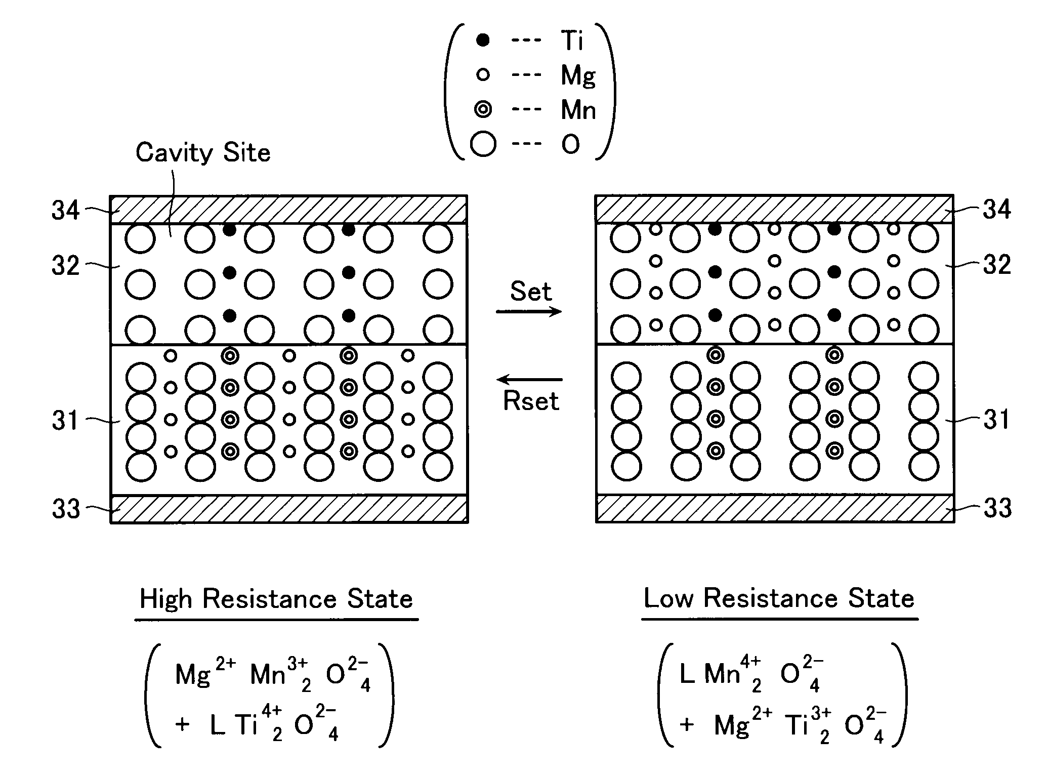
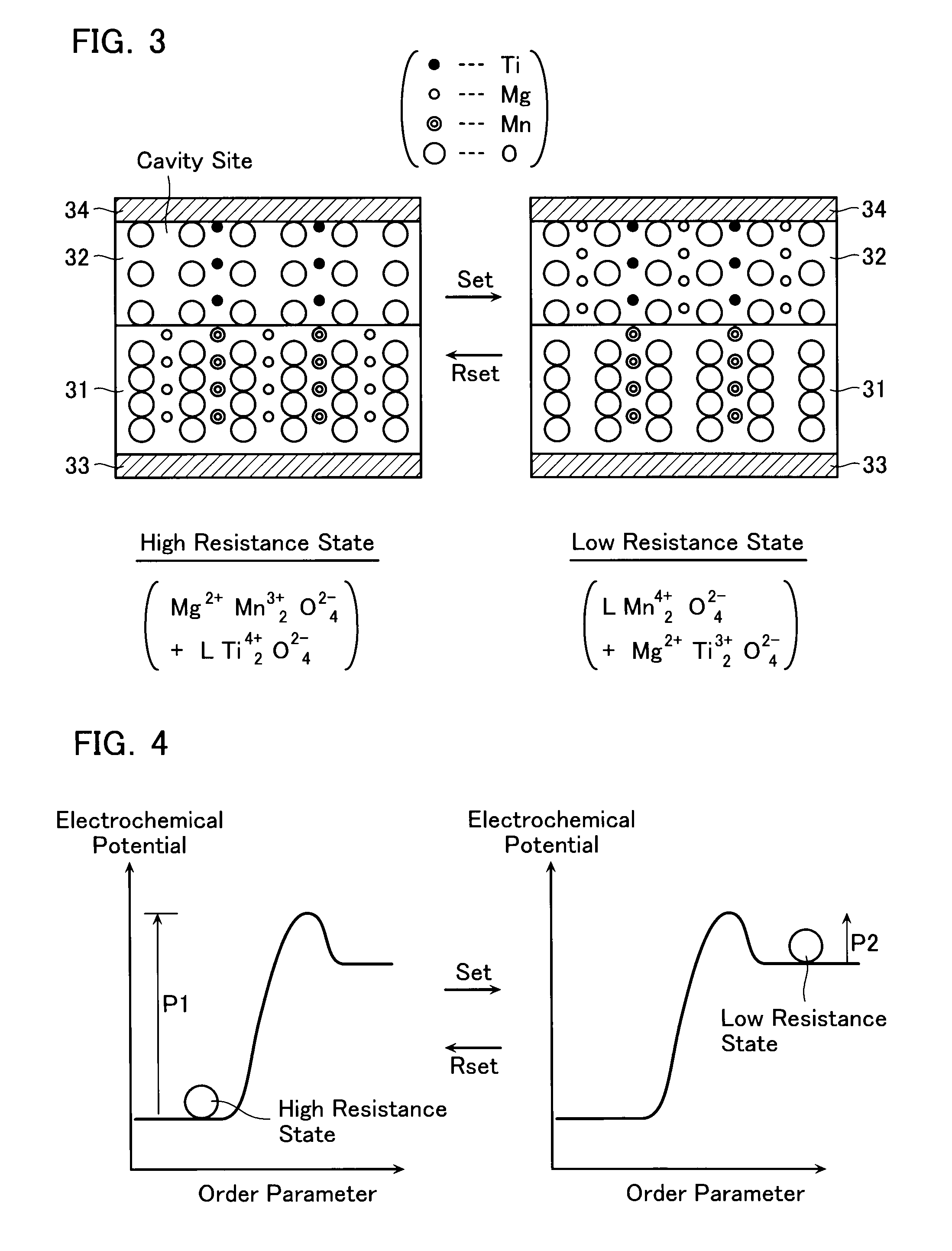

Embodiment Construction

[0027]Illustrative embodiments of this invention will be explained with reference to the accompanying drawings below.

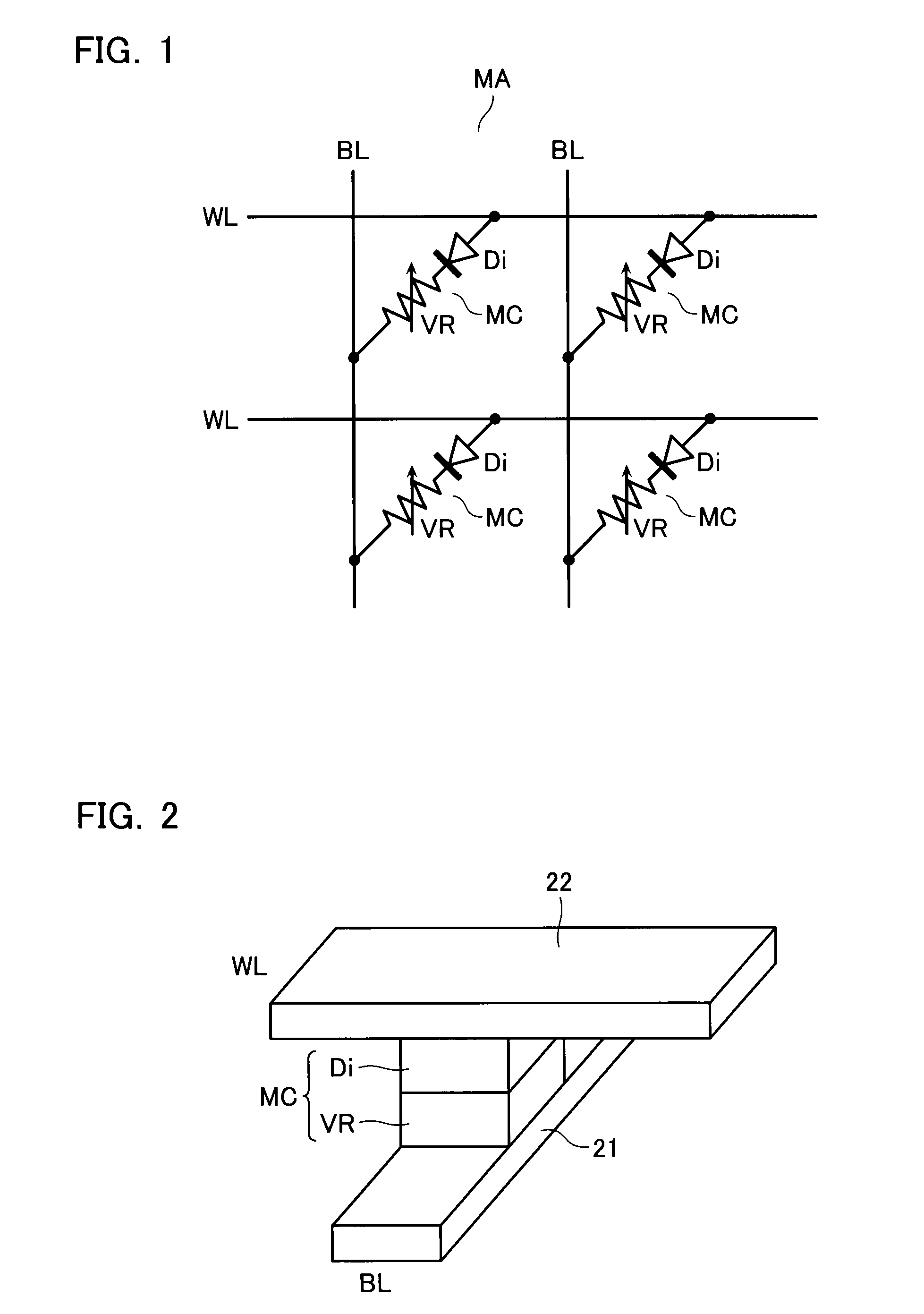
[0028]FIG. 1 shows an equivalent circuit of memory cell array MA in accordance with an embodiment. As shown in FIG. 1, word lines WL and bit lines BL are disposed to cross each other, and resistance change memory cells MC. Memory cell MC is formed of access element, e.g., diode, Di and variable resistance element VR, which are connected in series and disposed at a cross point between word line WL and bit line BL.

[0029]Variable resistance element VR has a stacked structure of electrode / transition metal oxide / electrode. In accordance with voltage, current or heat application condition, the resistance value of the metal oxide layer is changed, so that the element VR stores one of different resistance states as data in a non-volatile manner. This kind of variable resistance element VR is formed to be operable as a bipolar type of or a unipolar type of element. The cell ar...


PUM


Abstract

A resistance change memory device includes: a memory chip having memory cells of a resistance change type; and a heater so attached to the memory chip as to apply a temperature bias to the memory chip.

Description

CROSS-REFERENCE TO RELATED APPLICATION[0001]This application is based on and claims the benefit of priority from the prior Japanese Patent Application No. 2007-171939, filed on Jun. 29, 2007, the entire contents of which are incorporated herein by reference.BACKGROUND OF THE INVENTION[0002]1. Field of the Invention[0003]This invention relates to a resistance change memory device, in which memory cells of a resistance-change type are used, and an integrated circuit device with a resistance change memory chip.[0004]2. Description of the Related Art[0005]A resistance change memory device has been proposed to store a resistance value as data, which is reversibly rewritten by applying voltage, current or heat, and it is noticed for succeeding to the conventional flash memory. This resistance change memory is suitable for miniaturizing the cell size, and for constituting a cross-point cell array. In addition, it is easy to stack cell arrays.[0006]As a heat process adapted for resetting a ...

Claims


Application Information

Patent Timeline
Patent Type & Authority Applications(United States)
IPC IPC(8): G11C11/21
CPCG11C7/04G11C13/00G11C2013/008G11C13/0069G11C13/0004
Inventor TAKASE, SATORU
Owner KK TOSHIBA
Learn More