
User selection method and user selection device for multiuser MIMO communication

a multi-user, multi-user technology, applied in the direction of frequency-division multiplex, transmission monitoring, instruments, etc., can solve the problem of not providing a fair distribution (data transmission opportunity) of the selection frequency to each user, the amount of calculation becomes massive, and the multi-user diversity effect cannot be satisfactorily provided. achieve the effect of large multi-user diversity

Active Publication Date: 2009-01-08
NEC CORP
View PDF2 Cites 14 Cited by
  • Summary
  • Abstract
  • Description
  • Claims
  • Application Information

AI Technical Summary

Benefits of technology

[0030]An object of the present invention is to provide a user selection method and a device which can provide a satisfactory, multiuser diversity effect with a small amount of calculation.
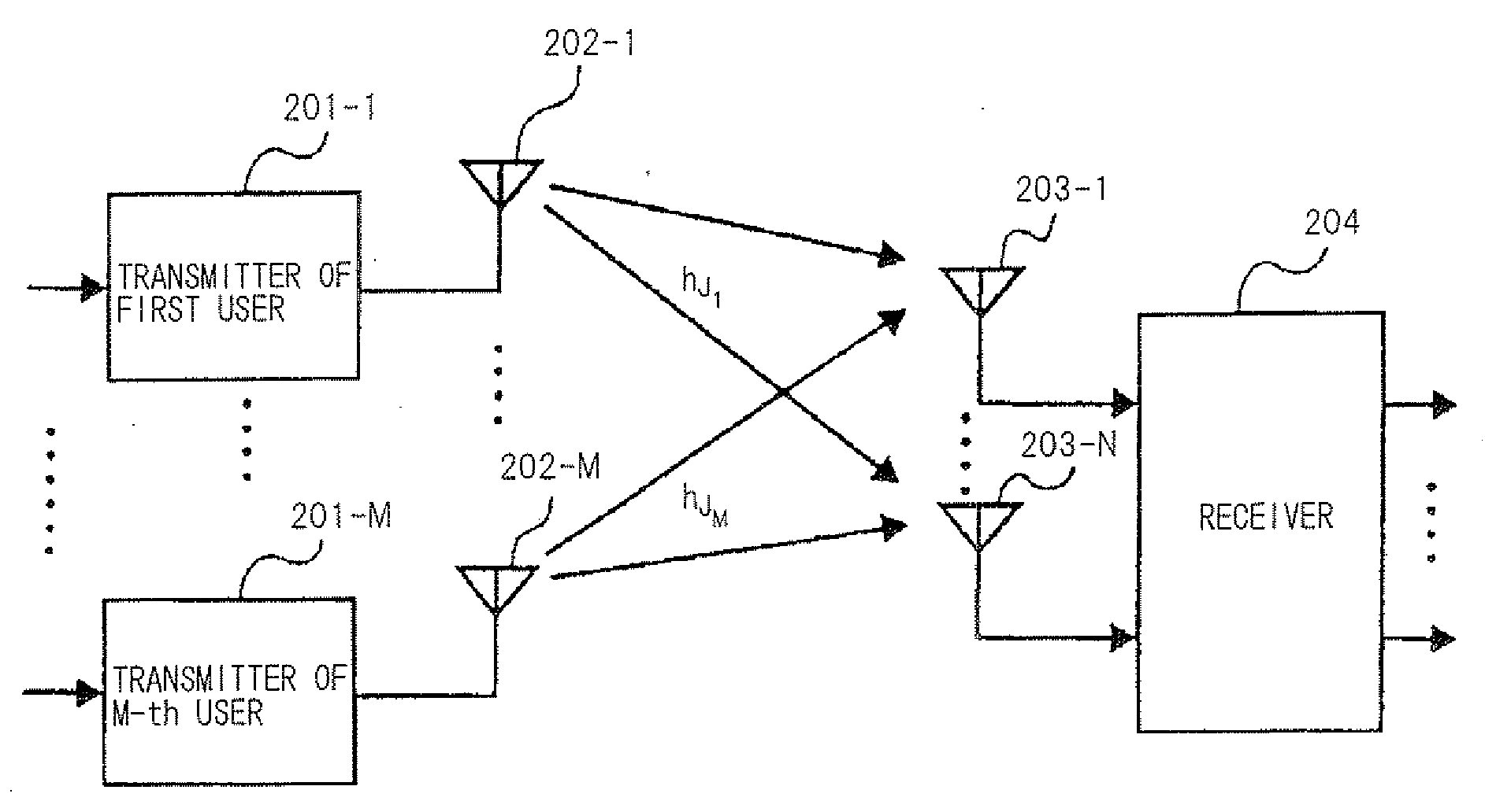
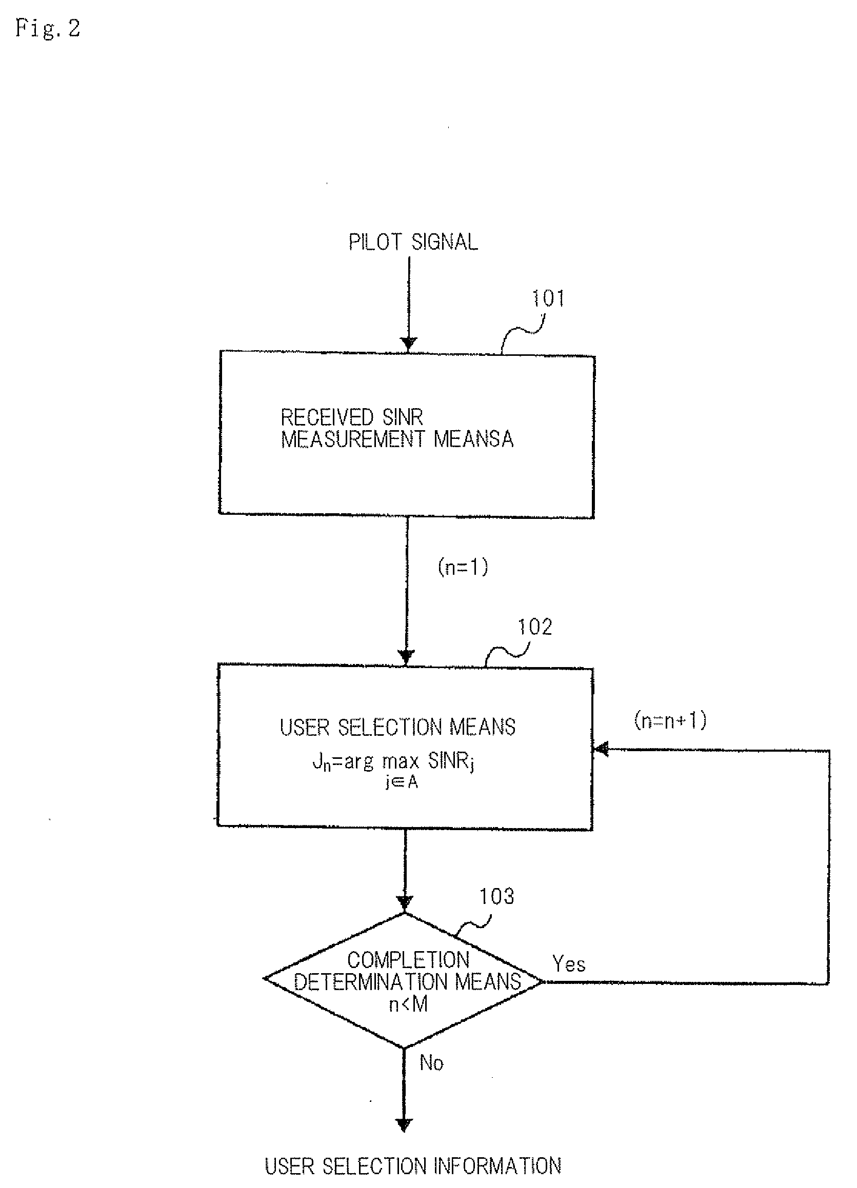
[0044]In the present invention, the received SINR is corrected with the orthogonal coefficient calculated based on the GS orthogonalization for each MIMO multiplexed layer, and using this correction SINR, a user is selected in sequence, and thereby a large, multiuser diversity effect can be provided with a small amount of calculation.

Problems solved by technology

The user selection method according to the maximum CIR method can achieve the multiuser diversity effect to the maximum extent by selecting a user having a good channel quality, but does not provide fair distribution (data transmission opportunity) of the selection frequency to each user.
As described above, the user selection methods based on the received SINR (the maximum CIR method and the PF method) have a problem that the multiuser diversity effect cannot be satisfactorily provided because the channel orthogonality of a pair of users is not considered.
The user selection method by the whole search method can provide a satisfactory multiuser diversity effect, but has a problem that the amount of calculation becomes massive as the number of all users and the number of simultaneous transmission users are increased.
The user selection method by the GS orthogonalization method has a problem that interference power is not considered because of a signal power criterion based on the projection channel power of each user.

Method used


Image

  • User selection method and user selection device for multiuser MIMO communication
  • User selection method and user selection device for multiuser MIMO communication
  • User selection method and user selection device for multiuser MIMO communication

Examples


Embodiment Construction

[0056]Next, exemplary embodiments of the present invention will be described with reference to the accompanying drawings.

[0057]FIG. 9 shows a configuration of one exemplary embodiment of a device for user selection by a CA method of the present invention.

[0058]The user selection in the present exemplary embodiment is executed by using received SINR / channel vector measurement means 1, orthogonal coefficient calculating means 2, correction SINR calculating means 3, user selection means 4, completion determination means 5, and projection vector updating means 6. The user selection method is a method that a received SINR is corrected with an orthogonal coefficient calculated based on GS orthogonalization for each MIMO multiplexed layer by each TTI, and a user having a large correction SINR is selected.

[0059]Received SINR / channel vector measurement means 1 measures the received SINR and a channel vector in up-link by using a pilot signal of each user (mainly the pilot signal for sounding...


PUM


Abstract

The present invention aims to provide a user selection method which can provide a large, multiuser diversity effect with a small amount of calculation in multiuser MIMO systems, the method being a user selection method for multiuser MIMO communication, in which an orthogonal coefficient is calculated using a received SINR from a projection channel vector by using GS orthogonalization, and using the orthogonal coefficient, a correction SINR is calculated, and using this correction SINR, user selection is performed, and for a next user selection, the projection channel vector is updated, and the above processes are applied to all users.

Description

[0001]This application is based upon and claims the benefit of priority from Japanese patent application No. 2007-174110, filed on Jul. 2, 2007, the disclosure of which is incorporated herein in its entirety by reference.BACKGROUND OF THE INVENTION[0002]1. Field of the Invention[0003]The present invention relates to a user selection method for multiuser MIMO communication.[0004]2. Description of the Related Art[0005]In up-link wireless access of Next Generation Mobile Communication Systems, to improve cell throughput, multiuser Multiple Input Multiple Output (MIMO) communication (hereinafter, called “MU-MIMO”) may be expected to be used. In MU-MIMO, multiple terminals transmit data signals at the same frequency and a base station separates transmitted signals of multiple users which are viewed as MIMO signals. MU-MIMO may be viewed as a Space Division Multiple Access (SDMA) system in which a space channel forms a resource in addition to traditional resources of time and frequency, a...

Claims


Application Information

Patent Timeline
IPC IPC(8): H04B1/10H04B7/04H04J99/00
CPCH04B7/0417H04B7/0632H04B7/0452
Inventor YOSHIDA, SHOUSEIKIMATA, MASAYUKI
Owner NEC CORP
Learn More