Method of inspecting outer wall of honeycomb structure body

a technology of honeycomb structure and outer wall, which is applied in the field of methods of detecting defects generated in the outer wall of the honeycomb structure body, can solve the problems of defect generation, defect failure, and various defects, and achieve the effect of stable inspection

Active Publication Date: 2009-01-08
NGK INSULATORS LTD
View PDF7 Cites 11 Cited by
  • Summary
  • Abstract
  • Description
  • Claims
  • Application Information

AI Technical Summary

Benefits of technology

[0012][5] The method of inspecting the outer wall of the honeycomb structure body according to any one of the above [1] to [4], including a step of binarizing the obtained image; a step of removing noise; and a step of judging whether or not the defect is present.
[0013]The method of inspecting the outer wall of the honeycomb structure body according to the present invention can be performed without relying on human sensory functions, and a defect detection level and an inspection time per honeycomb structure body are constant, so that stable inspection can be performed.

Problems solved by technology

However, in such manufacturing steps, various defects (cut, hole, crack, attachment of dust, dirt, uneven surface, scratch, mixing of foreign matters, and the like) are generated sometimes in the outer wall of the honeycomb structure body.
However, such a visual inspection is a sensory inspection based on a human visual sense, and hence the defect is missed in not a few cases.
Moreover, fluctuation is generated in a defect detection level owing to a difference in a visual power or a fatigue degree, and it is difficult to perform stable inspection.
Furthermore, fluctuation is generated in an inspection time per honeycomb structure body owing to the difference in the fatigue degree or a product dimension, and it is therefore difficult to perform the efficient and stable industrial production of the honeycomb structure body.
In addition, when the defect detection level has to be raised, the number of inspecting persons has to be increased, and the inspection time per honeycomb structure body has to be lengthened, so that productivity deteriorates.

Method used


Image

  • Method of inspecting outer wall of honeycomb structure body
  • Method of inspecting outer wall of honeycomb structure body

Examples


examples

[0026]The present invention will hereinafter be described in more detail in accordance with examples, but the present invention is not limited to these examples.

examples 1 to 18

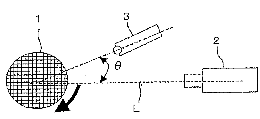
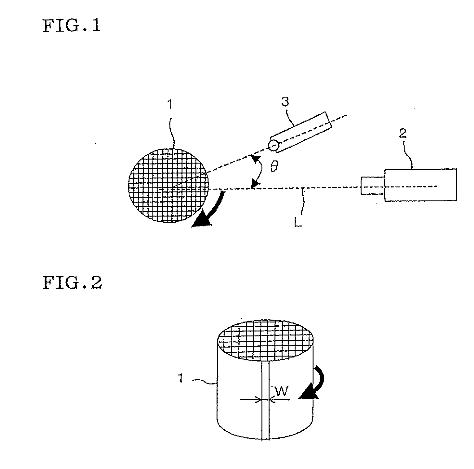
[0027]Fifteen sintered honeycomb structure bodies (sample Nos. 1 to 15) made of cordierite which had defects in the outer walls of the bodies or which did not have any defect in the outer walls as shown in Table 1 were prepared, and the outer walls of the honeycomb structure bodies (the sintered bodies) were inspected by an inspection method according to the present invention to judge a detectability and to check a time (tact time) required for the inspection of each of the honeycomb structure bodies. The central axis of the honeycomb structure body as an inspection target was matched with the rotary shaft of a turntable to mount the body on the turntable so that eccentricity during the rotation was within ±1.5 mm. As a line camera, a line camera having a driving frequency of 40 MHz and including 4000 pixels was used. While the turntable was rotated once in three seconds, the outer wall of the honeycomb structure body was imaged in a width of 15 μm every line. The imaging of the who...


PUM

PropertyMeasurementUnit
angleaaaaaaaaaa
imaging widthaaaaaaaaaa
driving frequencyaaaaaaaaaa

Abstract

There is disclosed a method of inspecting the outer wall of a honeycomb structure body which can be performed without relying on human sensory functions and in which a defect detection level and an inspection time per honeycomb structure body are constant, so that stable inspection can be performed. In a method of inspecting the outer wall of a honeycomb structure body 1 made of a ceramic material, while rotating the honeycomb structure body 1, the outer wall of the honeycomb structure body 1 is imaged by a line camera 2, and the thus obtained image is processed to judge whether or not a defect is present in the outer wall of the honeycomb structure body 1.

Description

TECHNICAL FIELD[0001]The present invention relates to a method of detecting a defect generated in the outer wall of a honeycomb structure body by use of image processing.BACKGROUND ART[0002]A honeycomb structure body is used as a filter which traps a particulate matter included in an exhaust gas from an internal combustion engine, a boiler or the like, a catalyst carrier of a catalyst for purifying the exhaust gas, or the like. In particular, a honeycomb structure body made of a ceramic material has excellent characteristics such as resistance to heat, resistance to thermal shock and resistance to oxidation, and is broadly used suitably for the above-mentioned application.[0003]In general, the honeycomb structure body made of the ceramic material is manufactured by kneading ceramic powder with an organic binder, water and the like to form clay, forming the clay into a honeycomb shape by an extrusion forming process or the like, subjecting the resultant material to drying, calcining ...

Claims


Application Information

Patent Timeline
Patent Type & Authority Applications(United States)
IPC IPC(8): G06K9/00
CPCG01N21/952
Inventor KOMAKI, TAKESHIYASUI, TADAYOSHI
Owner NGK INSULATORS LTD
Why Eureka
Try Eureka