Electronic device

Inactive Publication Date: 2009-01-08
SEIKO INSTR INC
View PDF6 Cites 75 Cited by
  • Summary
  • Abstract
  • Description
  • Claims
  • Application Information

AI Technical Summary

Benefits of technology

[0013]Therefore, in order to solve the aforementioned problems, in an electronic device of a structure where a transparent flat body is bonded to a full surface of a display device by an optica

Problems solved by technology

When the transparent flat body is entirely bonded to the display device of the structure where the display panel is fixed by a metal bezel using a light curable optical adhesive of a liquid type, there arise problems as described below.
In other words, if there is a gap between the display panel and the metal bezel, the adhesive is impregnated between the metal bezel and the display panel, and the impregnat

Method used


Image

  • Electronic device
  • Electronic device
  • Electronic device

Examples


embodiment 1

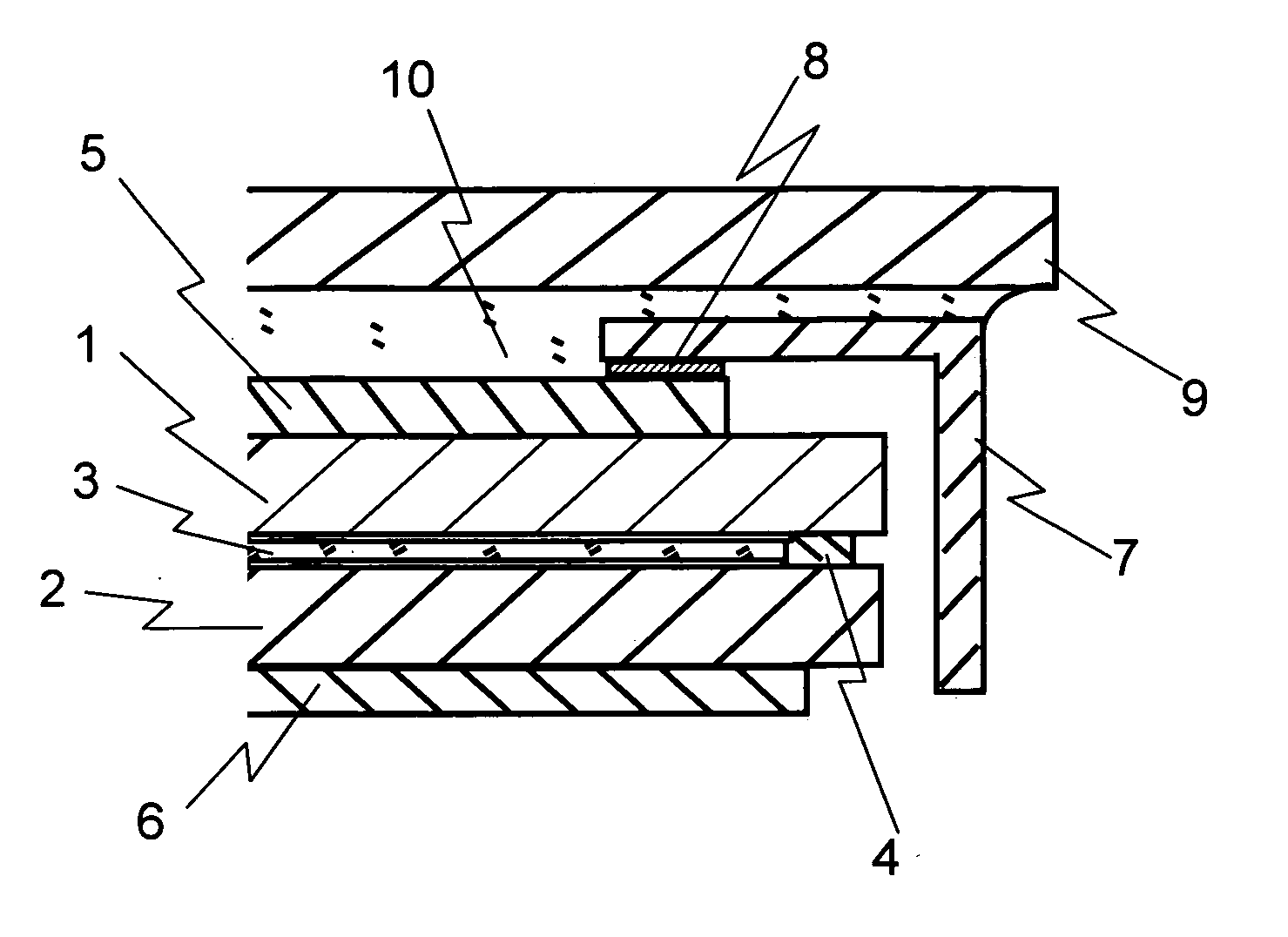
[0034]FIG. 1 schematically shows a cross-sectional structure of a liquid crystal display device used in this embodiment. An adhesive tape 8 is used as a resin for preventing infiltration. On a glass substrate 1 of a display unit side, a color filter is formed, and a thin film transistor (TFT) device is formed on a counter substrate 2. Liquid crystal 3 is sealed between the glass substrate 1 and the counter substrate 2 using a sealing compound 4. A light absorption polarizing plate 5 is provided on a surface of the glass substrate 1, an optical film 6 in which a light reflection polarizing plate and a light absorption polarizing plate are laminated is provided on a surface of the counter substrate 2.

[0035]Among light emitted from a backlight (not shown) disposed on a back side of the display panel, light emitted in one vibration direction permeates the optical film 6 and enters a liquid crystal layer. A molecular direction of the liquid crystal is controlled by an electrical signal a...

embodiment 2

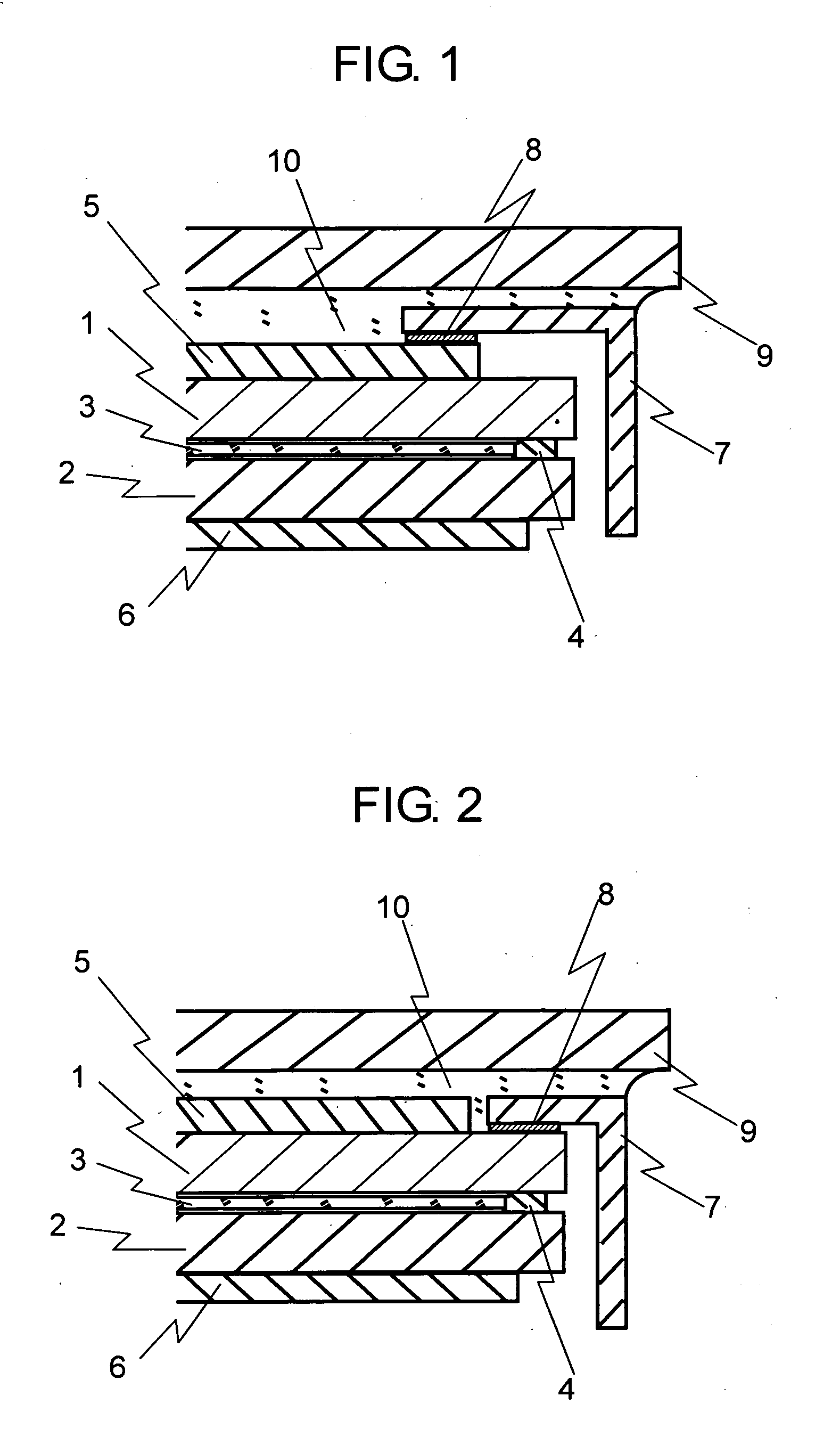
[0038]FIG. 2 schematically shows a cross-sectional structure of a liquid crystal display device used in this embodiment. The same components as the components of Embodiment 1 are denoted by the same reference numerals, and the overlapping description is omitted. Embodiment 2 is different from Embodiment 1 in that the adhesive tape 8 is provided between the metal bezel 7 and the glass substrate 1 of the display panel. The metal bezel 7 is fixed to the glass substrate 1 of the display surface side by the adhesive tape 8. The metal bezel 7 is bonded to the glass' substrate 1 without a gap by the adhesive tape 8. The transparent plate 9 made of the strengthened glass is entirely bonded to the liquid crystal display device including the display unit and the metal bezel by the light curable adhesive 10. In this case, the polarizing plate 5 has a smaller size compared with the glass substrate 1.

[0039]The liquid light curable adhesive before curing does not penetrate the adhesive tape 8, an...

embodiment 3

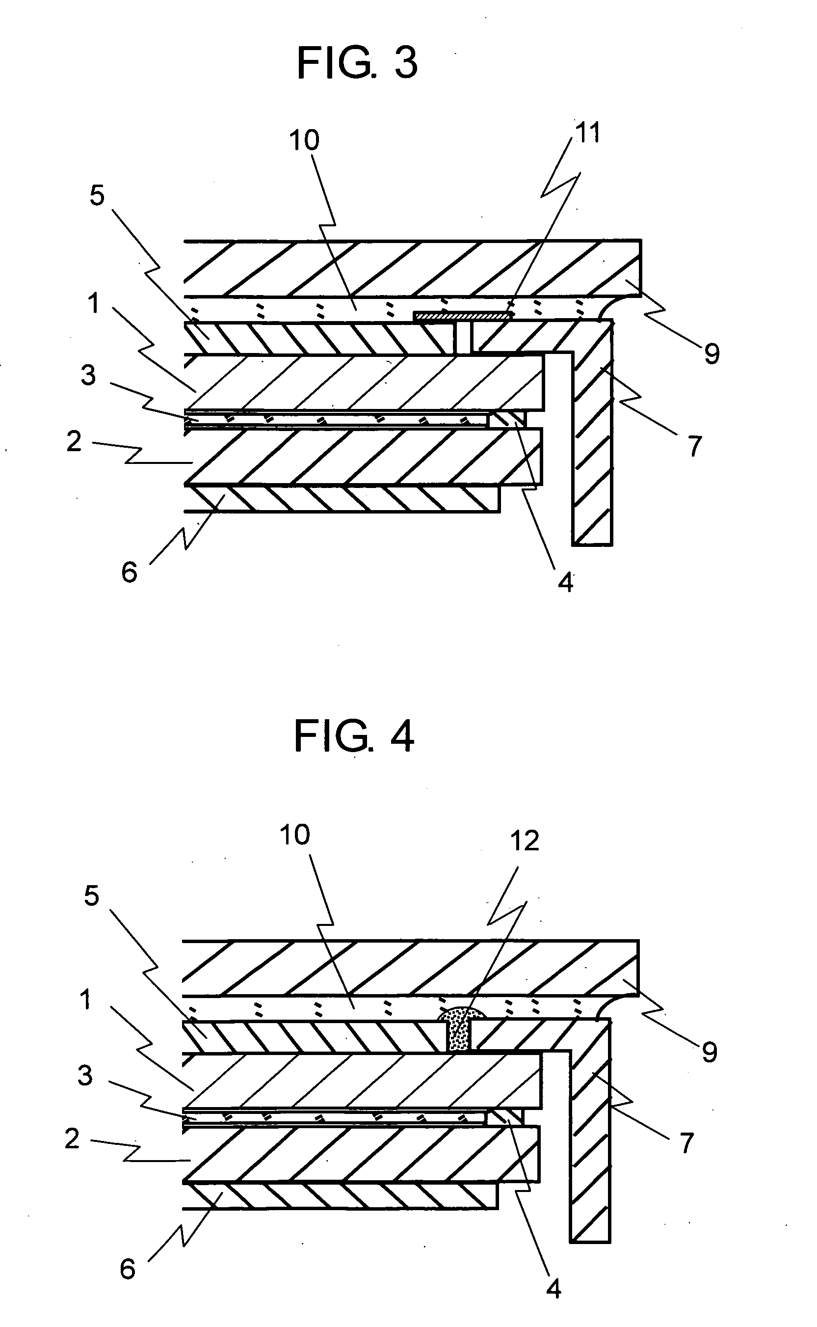
[0040]FIG. 3 schematically shows a cross-sectional structure of a liquid crystal display device used in this embodiment. The same components as the components of the aforementioned embodiments are denoted by the same reference numerals, and the overlapping description is omitted. Embodiment 3 is different from the aforementioned embodiments in a fixation structure of the metal bezel 7. The metal bezel 7 is brought into contact with a periphery portion of the surface of the glass substrate 1, and is fixed to the frame (not shown) of the backlight by a screw or fitting. Further, a tape 11 including a polyethylene terephthalate (PET) base material is attached to the metal bezel 7 and the polarizing plate 5 of the display panel over an entire periphery thereof from the above. The transparent plate 9 is entirely bonded to the liquid crystal display device of the aforementioned structure including the display unit and the metal bezel by curing the liquid light curable adhesive 10. Here, t...


PUM

PropertyMeasurementUnit
Electrical conductivityaaaaaaaaaa
Electrical conductoraaaaaaaaaa
Transparencyaaaaaaaaaa

Abstract

Provided is an electronic device in which a display panel fixed by a metal bezel is entirely bonded to a touch panel or a transparent plate for protection with a liquid adhesive so that the liquid adhesive is prevented from permeating a gap between the metal bezel and the display panel. In other words, the display panel is adhered to the metal bezel by providing an adhesive or the like there between. The display device of the aforementioned structure is bonded to the touch panel or the transparent plate for protection by filling an entire surface of the gap there between with a liquid transparent adhesive. Further, the adhesive or the like is made to have conductivity, and a transparent conductive film is formed on a surface of the display panel, whereby the transparent conductive film is electrically connected to the metal bezel, which provides counter-measures against static electricity.

Description

BACKGROUND OF THE INVENTION[0001]1. Field of the Invention[0002]The present invention relates to a method and a structure for entirely bonding a transparent plate for protection or a transparent touch panel to a display device with a liquid adhesive. For instance, the present invention relates to a structure, in a device such as a cell phone, for bonding the transparent plate for protection or the touch panel to a front surface of the display device. For the transparent plate for protection, a material such as polycarbonate; acrylic, alkali-free glass, soda-lime glass, chemically strengthened glass, air-cooled strengthened glass, or sapphire glass is used. Depending on products, a frame-like printing may also be formed on the transparent plate for protection. As to the touch panel, there are various types such as an analog resistive touch panel, a digital resistive touch panel, an ultrasonic touch panel, an optical touch panel, an acoustic touch panel, an electromagnetic induction t...

Claims


Application Information

Patent Timeline
IPC IPC(8): B32B5/00G02F1/1333G02F1/1335G09F9/00
CPCG02F1/133308G02F2001/13332Y10T428/24777G02F2202/28G02F2001/133334G02F1/13332G02F1/133334
Inventor MATSUHIRA, TSUTOMU
Owner SEIKO INSTR INC
Why Eureka
Try Eureka