Circulation of Gas-Entrained Fuel Cell Coolant

a fuel cell and gas-entrained technology, applied in the field of gas-entrained fuel cell coolant circulation, can solve the problems of reduced performance, reduced cooling or water flow rate in the cells, and degradation of components, so as to improve the hydration of pem fuel cells, reduce gas ingestion, and improve the effect of gas venting

Active Publication Date: 2009-01-08
AUDI AG
View PDF14 Cites 6 Cited by
  • Summary
  • Abstract
  • Description
  • Claims
  • Application Information

AI Technical Summary

Benefits of technology

[0005]Aspects of the invention include: assuring coolant flow in small fuel cell coolant or water management passageways; mitigating bubble blockage in low-flow fuel cell coolant or water management passageways; assisting gas bubbles to flow through coolant or water management passageways in PEM fuel cells; improved venting of gas in PEM fuel cell coolant or water management passageways; reducing excessive ingestion of gas into fuel cell coolant or water management passageways; increasing gas flow toward a vent in PEM fuel cells; improved hydration in PEM fuel cells; improved evaporative cooling in PEM fuel cells; and reducing the number of components in the fuel cell power plant which have rotating parts.

Problems solved by technology

However, in systems which do not use either a coolant pump or a gas venting micropump, and have minimal external water plumbing, the flow rate of coolant or water in the cells is quite low.
The dehydration allows gas to enter the coolant flow channels at too high a rate, sometimes referred to as “gas breakthrough” of the water transport plates, thereby causing localized heating and dehydration of the membrane at various spots, resulting in degradation of components and reduced performance.
AWM fuel cells may also have extremely small, in-cell water passageways to provide low flows of water to the anode side and / or cathode side of the fuel cells for water management, with insignificant cooling resulting from the water flow.

Method used


Image

  • Circulation of Gas-Entrained Fuel Cell Coolant
  • Circulation of Gas-Entrained Fuel Cell Coolant
  • Circulation of Gas-Entrained Fuel Cell Coolant

Examples


Embodiment Construction

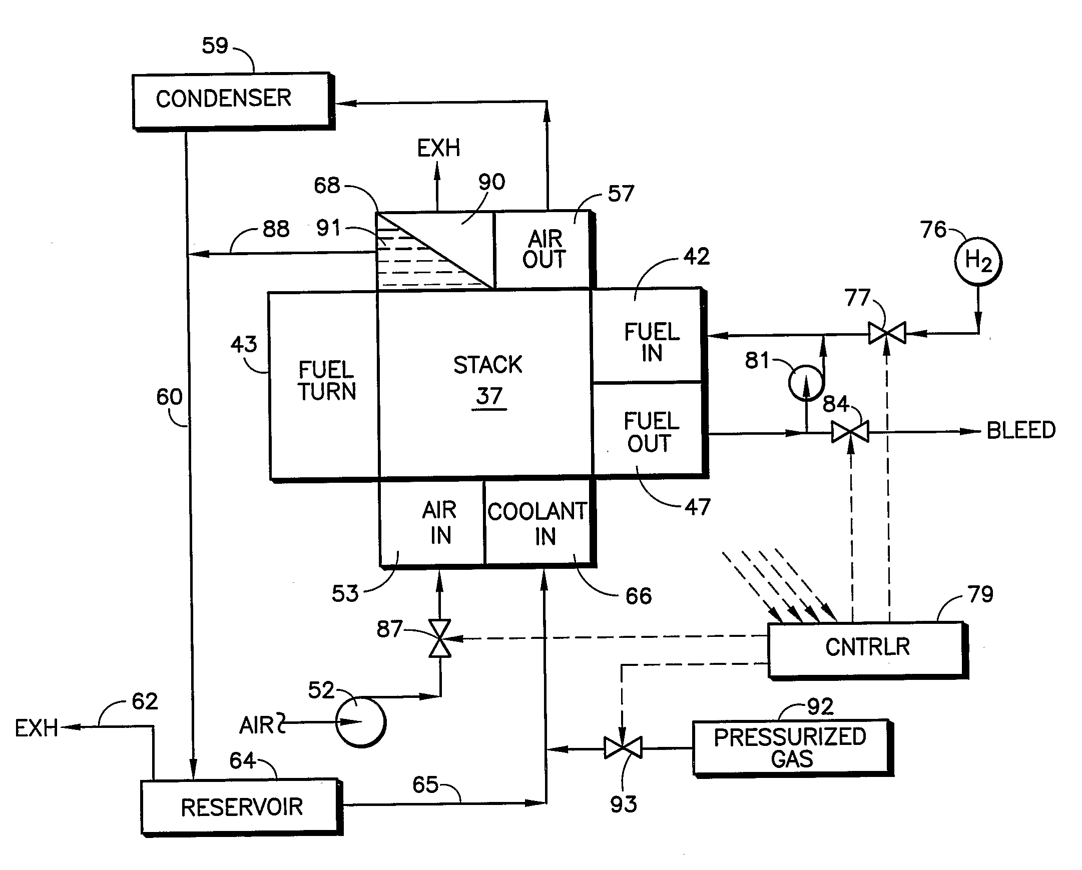
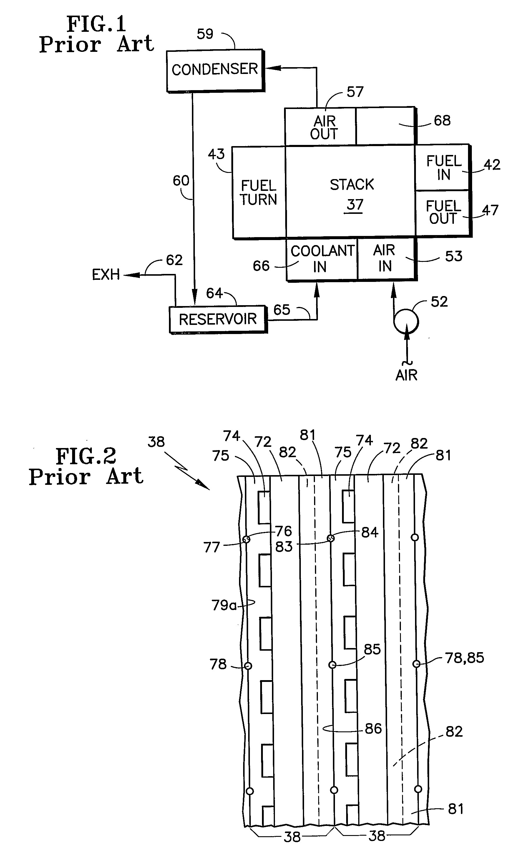
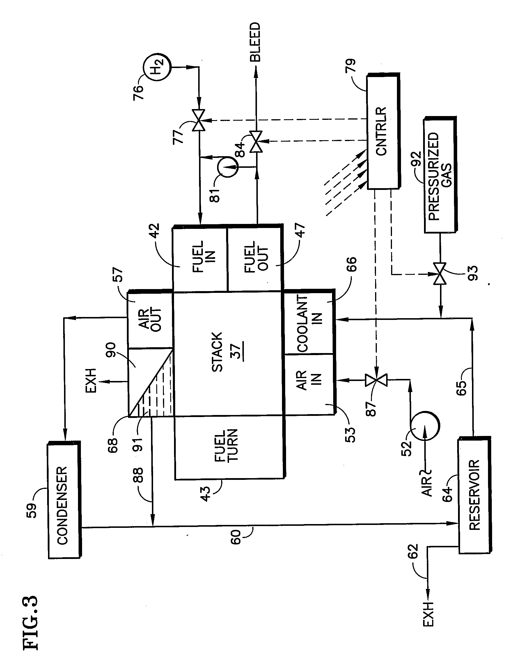
[0027]A fuel cell system employing evaporative cooling is disclosed in U.S. Ser. No. 11 / 230,066 filed Sep. 19, 2005, and described with respect to FIGS. 1 and 2 herein. In the aforementioned application, a fuel cell stack 37 receives fuel from an inlet 42; the fuel passes to the left in a first half of the fuel flow field and then is returned by a fuel turn manifold 43 to pass to the right through the other half of the stack and through a fuel outlet 47. Air is pumped through an air inlet 53 by an air pump 52 into the oxidant reactant gas (air) flow fields in the stack 37; water evaporates into the air, thereby cooling the fuel cells 38 (FIG. 2). The outflow 57 of the oxidant reactant gas channels passes through a condenser 59 wherein heat is removed and the water is recovered and returned over a conduit 60 to a water / gas separator which also serves as a reservoir 64. Any gas in the water is removed through exhaust 62. The water returns over a conduit 65, through coolant inlets 66 i...


PUM

PropertyMeasurementUnit
velocityaaaaaaaaaa
pressureaaaaaaaaaa
hydrophilicaaaaaaaaaa

Abstract

Coolant velocity greater than zero everywhere within the coolant channels (78, 85) of fuel cells (38) in a fuel cell stack (37) is assured by providing a flow of gas in the coolant channels, the flow being created by gas pressure from a source (92) of pressurized gas, an oxidant reactant air pump (52), a source (75) of hydrogen-containing fuel, or the fuel outlet (47), or the outflow of a condenser (59). Positive pressure may be applied to the coolant inlet (66) or negative pressure from an eductor (97) may be applied to a gas outlet (90) of the coolant channels, or both. Using gas to induce flow within the coolant channels eliminates the need for a bubble-clearing liquid pump and reduces liquid inventory and other plumbing; this makes the fuel cell power plant more freeze tolerant. Biphase flow from the condenser, which may be a vehicle radiator (120), renders the coolant return flow more freeze tolerant. Separate cooler plates (122) may be used with a coolant management system (125).

Description

TECHNICAL FIELD[0001]This invention relates to reducing gas bubble blockage in small, low flow coolant or water management passageways in fuel cells, by flowing sufficient gas, such as air or depleted reactant exhaust, to ensure a liquid velocity greater than zero everywhere in the coolant channels.BACKGROUND ART[0002]In order to reduce the exposure of proton exchange membrane (PEM) fuel cells to problems resulting from freezing temperatures, and to reduce reliance on water pumps and other plumbing as accessories to the fuel cells, the total volume of coolant in the fuel cells may be reduced.[0003]However, in systems which do not use either a coolant pump or a gas venting micropump, and have minimal external water plumbing, the flow rate of coolant or water in the cells is quite low. If only gas is vented from the coolant or water passageways, the flow is limited by the amount of water which evaporates into the reactant gases. With small passageways and low water flow, gas bubbles m...

Claims


Application Information

Patent Timeline
Patent Type & Authority Applications(United States)
IPC IPC(8): H01M8/04H01M8/00
CPCH01M8/04029H01M8/04044H01M8/04074H01M8/04097H01M8/04164H01M8/04179H01M8/04014H01M8/04291H01M2008/1095H01M2250/20Y02T90/32Y02E60/50H01M8/04253Y02T90/40
Inventor PERRY, MICHAEL L.DARLING, ROBERT M.
Owner AUDI AG
Why Eureka
Try Eureka