Method of shortening photoresist coating process

Inactive Publication Date: 2009-01-08
UNITED MICROELECTRONICS CORP
View PDF6 Cites 3 Cited by
  • Summary
  • Abstract
  • Description
  • Claims
  • Application Information

AI Technical Summary

Benefits of technology

[0007]Accordingly, the invention provides a method of shortening a photoresist coating process, which can decrease the cycle time and increase the operation efficiency of the coating machine.
[0014]Since the dummy dispense operation of the second photoresist liquid is done within the period of the backend part of the first coating operation, the cycle time of the whole photoresist coating process is reduced, so that the throughput and the operation efficiency of the coating machine both can be increased.

Problems solved by technology

This not only increases the cycle time of the process and reduces the throughput, but also lowers the operation efficiency of the coating machine.

Method used


Image

  • Method of shortening photoresist coating process
  • Method of shortening photoresist coating process
  • Method of shortening photoresist coating process

Examples


Embodiment Construction

[0019]The following embodiment is intended to further explain this invention but not to limit the scope of the same.

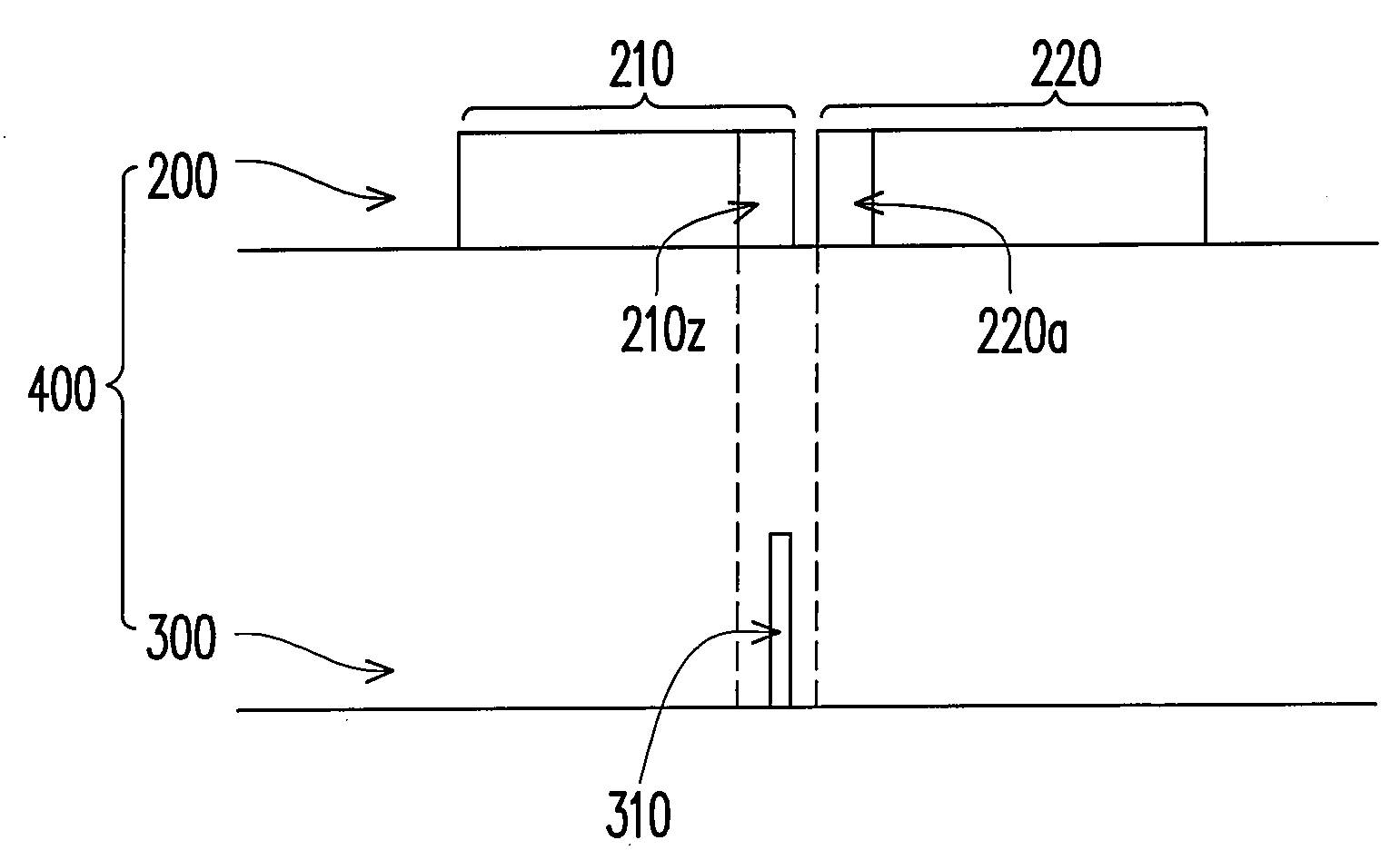
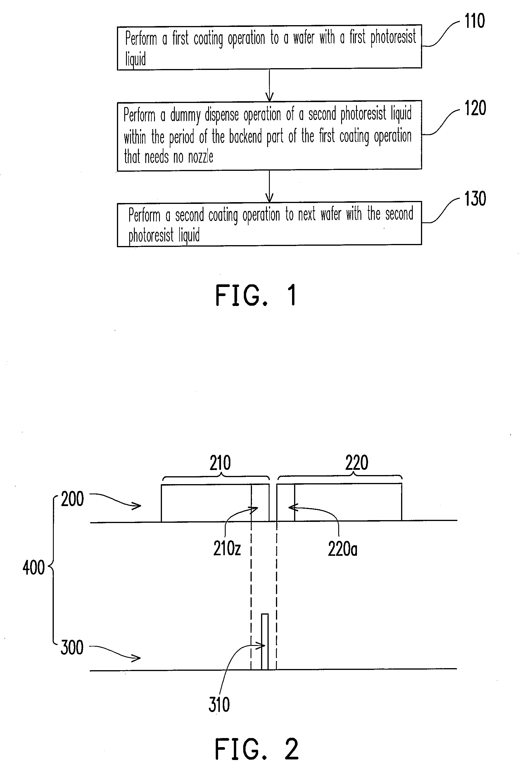
[0020]The method of this invention is applied to a photoresist coating process for a plurality of wafers. Referring to FIG. 1, in the first step 110, a first coating operation is performed to a wafer with a first photoresist liquid. Referring to FIG. 2, the photoresist coating process 400 may include a coating section 200 and a dummy dispense operation 300, wherein the coating section 200 includes a first coating procedure 210 using the first photoresist liquid and a second coating procedure 220 using a second photoresist liquid. The coating section 200 may further include an idle time (not shown) for wafer replacement. The above wafer may be the last-coated one of one lot or one section of wafers predetermined to coat with the first photoresist liquid, wherein the one section of wafers belong to one lot of wafers that include multiple sections of wafers. In general, t...


PUM


Abstract

A method of shortening a photoresist coating process for a plurality of wafers is provided, wherein the photoresist coating process includes a first coating operation to a first wafer using a first photoresist liquid and a second coating operation to a second wafer using a second photoresist liquid. The method includes performing a dummy dispense operation of the second photoresist liquid within the period of the backend part of the first coating operation that needs no nozzle.

Description

BACKGROUND OF THE INVENTION[0001]1. Field of Invention[0002]This invention relates to an integrated circuit (IC) process, and more particularly to a method of shorting a photoresist coating process.[0003]2. Description of Related Art[0004]Photoresist material is a photosensitive material needed in a lithography process, while a lithography process is essential for definition of the patterns of a film or doped regions. Therefore, the photoresist material is very important in IC processes.[0005]A lithography process typically includes coating a photoresist layer on a wafer, projecting light to the photoresist through a photomask to selectively photosensitize and transfer patterns to the same and then performing a development step. The photoresist coating step is accomplished in a machine equipped with a coater.[0006]Generally, a dummy dispense operation is performed before each lot of wafers is coated with photoresist to prevent the nozzle from drying and purge the tip photoresist liq...

Claims


Application Information

Patent Timeline
IPC IPC(8): H01L21/31
CPCH01L21/6715G03F7/162
Inventor CHEN, CHIUN-SHOWCHUNG, CHAO-YINGCHEN, JU-TEWU, CHAO-HSIEN
Owner UNITED MICROELECTRONICS CORP
Why Eureka
Try Eureka