State Based Birth Monitoring System

a state-based, birth monitoring technology, applied in the field of birth monitoring, can solve the problems of 50% false positive rate, inability to determine and inability to accurately identify the state of the birth process

Inactive Publication Date: 2009-01-08
BARNEV
View PDF58 Cites 34 Cited by
  • Summary
  • Abstract
  • Description
  • Claims
  • Application Information

AI Technical Summary

Benefits of technology

[0056]A broad aspect of some embodiments of the invention relates to automatic analysis of collected positional information relating to the position of parts of the cervix and / or fetal head. In an exemplary embodiment of the invention, the analysis includes comparing an input, such as a contraction strength signal, to an output (result) of the contraction, such as motion vector of a fetal head. In an exemplary embodiment of the invention, the analysis makes use of the fact that information is available more accurately and / or more often than by manual measurement, including during contractions.
[0058]As used herein the term “state” relates to a step or condition in a birth process which is identifiable. As will be noted below, some states are dynamic in that various parameters change during the state. For example, during an “acceleration stage” state, cervical dilatation increases. A static state, for example a “fetal engagement” state, generally indicates a clearly identifiable milestone in the birth process. As can be appreciated, it may be desirable, and is possible in some embodiments of the invention, to identify such static and / or dynamic states in a short time.
[0093]An aspect of some embodiments of the invention relates to displaying of information, for example, integrating physiological sensor information (non-geometric, such as pressure or heart rate) and geometrical information to provide meaningful results. In one example, a TOCO gauge or an IUP sensor are used to indicate the existence of a contraction, while geometrical information is used to assess its effect. In another example, geometrical information is used to calibrate or indicate a measurement problem in other sensors. In another example, the synchronization of events can be determined, for example, synchronization of fetal bradycardia with cervical dilatation. This may assist in indicating the cause of the bradycardia and / or suitable treatment.
[0098]In an exemplary embodiment of the invention, the displaying using statistical analysis is a concise manner of showing a current status of birth as compared to the general process. For example, showing a histogram of variation values as a function of cervical dilatation allows an easy determination if current measurements fit an existing pattern of the patient. In an exemplary embodiment of the invention, the use of a concise and / or statistical presentation allows the data to be normalized. In the example of the histogram, the shape of the distribution will be the same even if in a patient the cervical dilatation measurements are all off by a certain value or if the variation values in general for that patient are higher.
[0101]An aspect of some embodiments of the invention relates to apparatus for detecting the onset of a second stage of labor. In an exemplary embodiment of the invention, a device is mechanically coupled to a Cervical os and when that Cervical os retracts significantly relative to a reference point inside or outside the body, an indication is generated. In an exemplary embodiment of the invention, the device comprises a cervical anchor attached to a ruler, which ruler is long enough to exit the vagina. When the Cervical os retracts, the length of the ruler outside the body shortens. Optionally, an alarm is attached to the ruler, for example, the device including an element attached to the outside of the body, so that retraction of the ruler relative to the attachment element generates an audible and / or radio alarm. Such an alarm may be used to replace frequent (or too infrequent) manual checking of a patient's state.

Problems solved by technology

As the graph is an average for many births, even if a high rate of measurements is available, an identification of a state of the birth process will generally not be correct until well after the state has started.
Also, even when information is not compared to a graph, deciding on a state often takes an hour or more.
Also, in determining fetal distress, a decision is often made within a few minutes, however with a 50% false positive rate.

Method used


Image

  • State Based Birth Monitoring System
  • State Based Birth Monitoring System
  • State Based Birth Monitoring System

Examples


Embodiment Construction

State Based Monitoring Overview

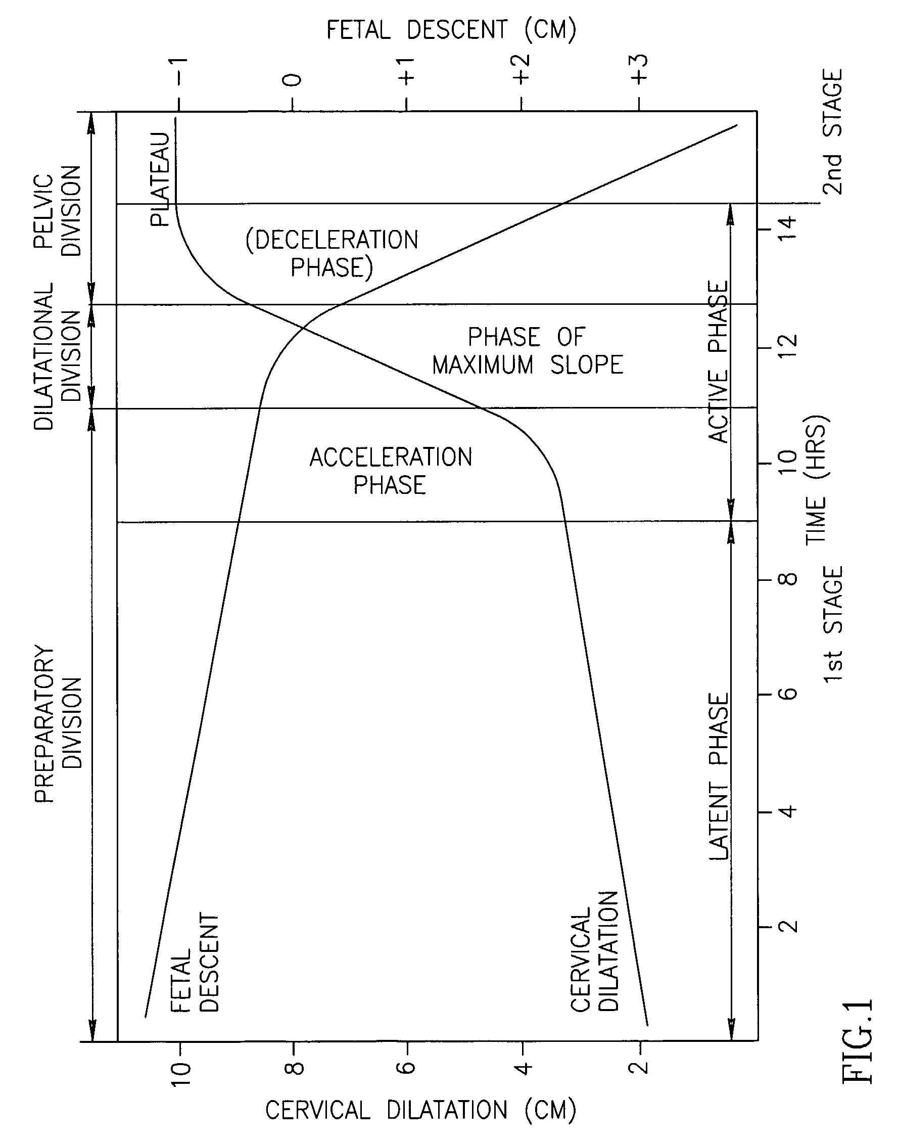
[0244]Referring back to FIG. 1, current practice is to chart the progress of a birth process along the graph of FIG. 1. As this graph is an average of many cases, a significant deviation must be detected if a caregiver is to be sure that there is a potential problem.

[0245]Even in non-pathological cases, this graph is problematic. As can be seen from the continuous and smooth nature of the graph, dilatation values cannot generally be used to identify the state of labor. Instead, an ongoing change or lack of change in dilatation values must be used (in the prior art). Further, as will be explained below, at large dilatation (>7 cm) the supposedly numerical values are actually symbolic values used to indicate an estimation of the labor progression. Thus, for example, even though an actual dilatation may be greater than 10 cm at maximum dilatation, an obstetrician will report “10 cm”. This results in a circular logic where an estimated state of labor is us...


PUM


Abstract

A method of monitoring a birth process, comprising: receiving, over time, a plurality of position signals from one or more positioning elements or tissue areas located at least one of a cervix and a fetal head; and determining a discrete state of labor of a fetus that is wholly inside a body responsive to said position signals, with a temporal resolution of better than 15 minutes, said discrete state being other than a start or stop of labor and encompassing more than a single contraction, said state including a state other than an abnormal fetal head position.

Description

RELATED APPLICATIONS[0001]The present application is a 119(e) of U.S. Provisional Application 60 / 560,291 filed on Apr. 7, 2004 the disclosure of which is incorporated herein by reference. The present application is also a continuation-in-part of PCT / IL2004 / 001092 filed on Nov. 29, 2004, the disclosure of which is incorporated herein by reference.FIELD OF THE INVENTION[0002]The present invention relates to the field of birth monitoring.BACKGROUND[0003]Most children are born by vaginal birth, and the vast majority of births at least in western countries, are carried out in a hospital under the monitoring of doctors and / or midwives. Among the main concerns of the medical staff during labor are to assess the progress of labor, to identify problems and complications and suggest and / or perform treatment to overcome these problems and complications as well as preventing or reducing damage to the mother and / or fetuses.[0004]The standard management of labor progress is using as a reference a...

Claims


Application Information

Patent Timeline
Patent Type & Authority Applications(United States)
IPC IPC(8): A61B5/103A61B5/00A61B5/117A61B8/08
CPCA61B5/0031A61B5/103A61B5/1116A61B2560/0223A61B5/6832A61B2503/02A61B8/0866A61B5/68335
Inventor SHARF, YEHUDA
Owner BARNEV
Why Eureka
Try Eureka