Method for Operating a Two-Stroke Engine

a two-stroke engine and engine technology, applied in the direction of electrical control, process and machine control, instruments, etc., can solve the problems of immediate stalling of the combustion engine, not only affecting the effect of kickback, and affecting the performance of the engin

Active Publication Date: 2009-01-08
ANDREAS STIHL AG & CO KG
View PDF7 Cites 11 Cited by
  • Summary
  • Abstract
  • Description
  • Claims
  • Application Information

AI Technical Summary

Benefits of technology

[0004]It is an object of the present invention to provide a method for operating a two-stroke engine with which a stable running of the engine can be achieved in a simple way.
[0008]For determining the ignition timing it is the therefore provided to take into consideration an engine speed as well as the number of engine cycles since the last combustion. In this way, the ignition timing can be selected optimally for an engine cycle such that the ignition timing is as advanced as possible but at the same time it is ensured that no kickback occurs. Whether combustion has taken place or not can be determined in a simple way based on the engine speed course of the internal combustion engine. In this way, for performing the method no additional devices such as additional sensors of the like are required.
[0018]It is provided that the control unit switches from a characteristic line for the second operating state to a characteristic line for the first operating state when at least one return condition is fulfilled. Expediently, the return condition is the actuation of a stop switch of the two-stroke engine. In this way it is ensured that the ignition timing when starting the engine is determined always based on the characteristic line for the starting state. Advantageously, a return condition is that the engine speed undershoots the self-sustaining engine speed. When the engine speed drops below a self-sustaining engine speed, the kinetic energy of the two-stroke engine is not sufficient to prevent a kickback at early ignition timings. In this connection it is provided that switching takes place to the characteristic line for the first operating state, i.e., the ignition timing is retarded. In this way, it is ensured that the piston is accelerated and no kickback can occur.

Problems solved by technology

It has been found that stalling of a two-stroke engine can be caused by the ignition timing at low engine speeds being advanced to such early ignition that kickback occurs, i.e. that the piston before reaching the top dead center is accelerated again toward bottom dead center, i.e., the crankshaft is driven in opposite direction.
This causes immediate stalling of the combustion engine.
It has been found that a kickback not only depends on the ignition timing and the engine speed but also on how strong the combustion is within the combustion chamber.
When the last combustion happened during the last engine cycle or only a few engine cycles back, the combustion chamber has not yet been well scavenged so that the combustion cannot be that strong.

Method used


Image

  • Method for Operating a Two-Stroke Engine
  • Method for Operating a Two-Stroke Engine
  • Method for Operating a Two-Stroke Engine

Examples


Embodiment Construction

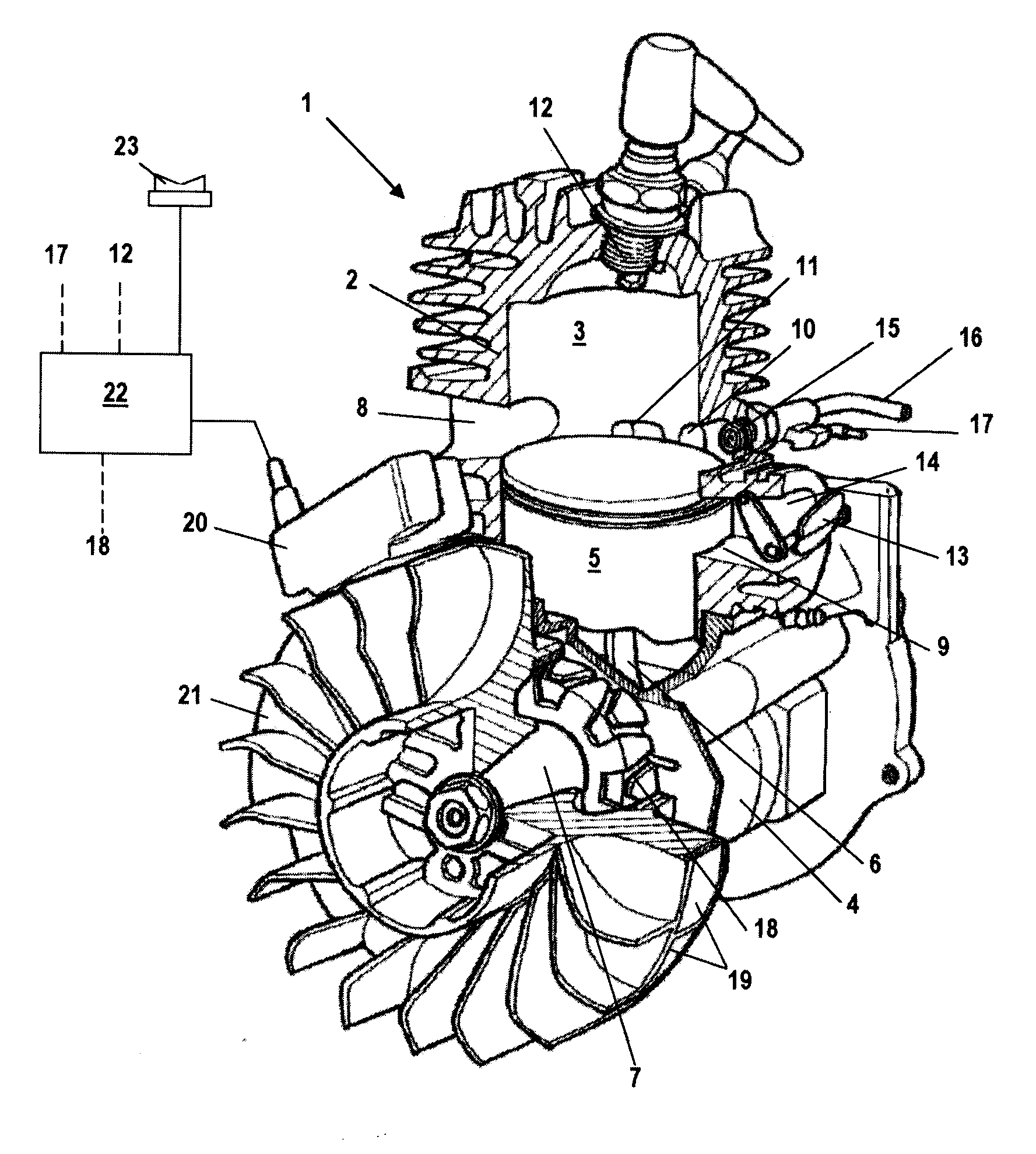
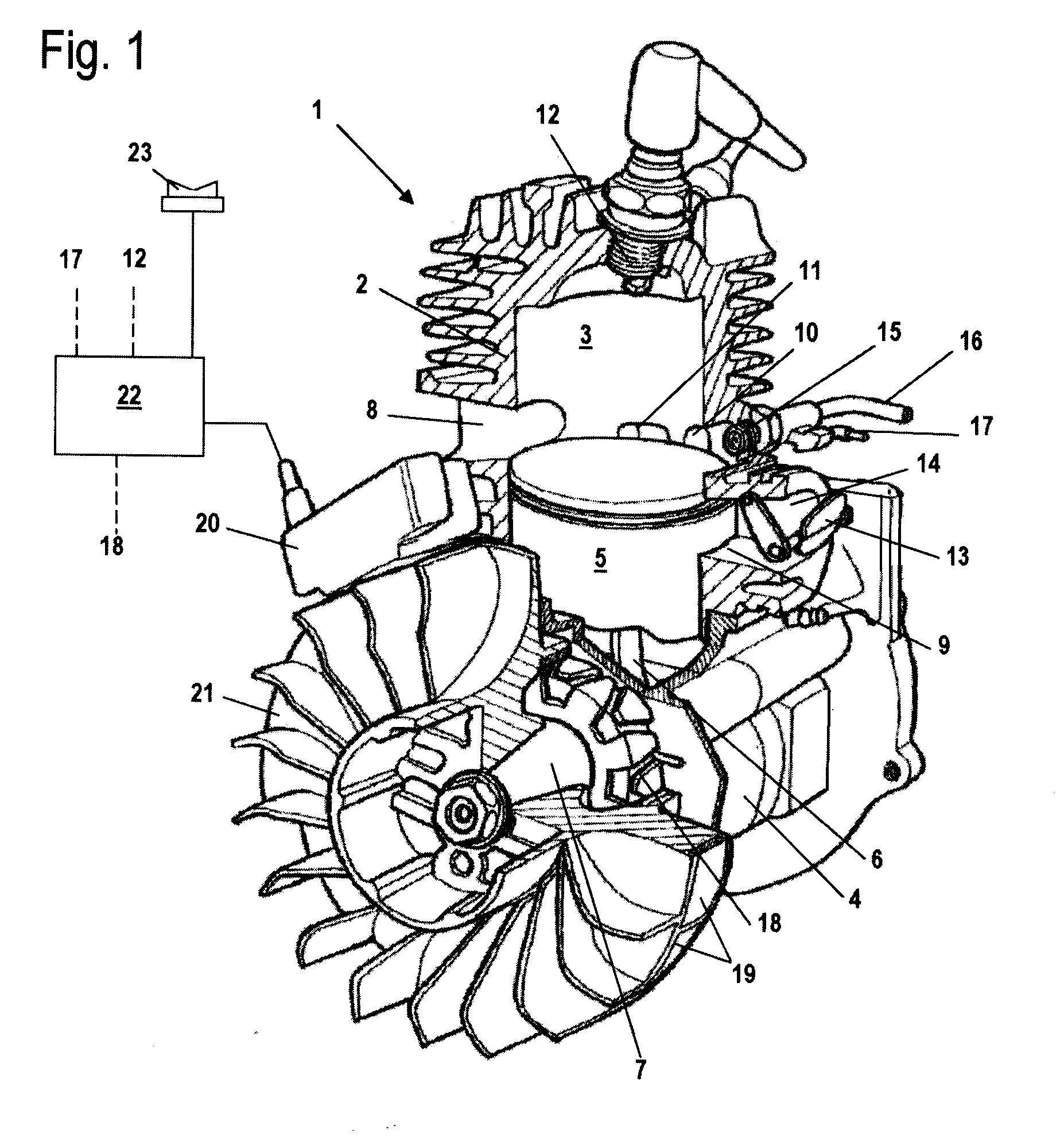
[0025]The two-stroke engine 1 illustrated in FIG. 1 is in particular a drive motor for a hand-held power tool such as a motor chainsaw, a cut-off machine, a trimmer or the like. The two-stroke engine 1 comprises a cylinder 2 with an internal combustion chamber 3. The internal combustion chamber 3 is delimited by a piston 5 that, by means of a connecting rod 6, drives in rotation a crankshaft 7 that is rotatably supported in the crankcase 4. A spark plug 12 projects into the internal combustion chamber 3 and is connected to a control unit 22 of a two-stroke engine 1. An exhaust port 8 is connected to the combustion chamber 3; the exhaust gases exit from the chamber 3 through the port 8. The two-stroke engine 1 has a total of four transfer passages 10 and 11 of which two are illustrated in FIG. 1. The four transfer passages are symmetrical to a center plane dividing the exhaust port 8. Two transfer passages 11 are provided proximal to the exhaust port 8 and two transfer passages 120 a...


PUM


Abstract

A two-stroke engine has a cylinder with a combustion chamber delimited by a reciprocating piston, wherein the piston drives in rotation a crankshaft, and wherein a spark plug projects into the combustion chamber and ignites a fuel / air mixture. The two-stroke engine further has devices for supplying fuel and combustion air to the combustion chamber and a control unit that determines the ignition timing based on an ignition map. The ignition map indicates the ignition timing as a function of the engine speed for at least one first and one second operating states and for at least one first and one second engine speed ranges. The engine is controlled in that for an engine cycle the ignition timing is set in the second operating state at least within the first engine speed range based on the engine speed and on the number of engine cycles since the last combustion.

Description

BACKGROUND OF THE INVENTION[0001]The invention relates to a method for operating a two-stroke engine that comprises a cylinder provided with a combustion chamber that is delimited by a reciprocatingly supported piston. The piston drives in rotation a crankshaft. A spark plug projects into the combustion chamber and ignites a fuel / air mixture in the combustion chamber. Devices for supplying fuel and combustion air into the combustion chamber are provided. A control unit determines ignition time by means of an ignition map wherein the ignition map indicates the ignition timing as a function of the engine speed for at least a first and a second operating states and for at least a first and a second engine speed ranges.[0002]DE 38 17 471 C1 discloses a method for operating a two-stroke engine in which the ignition timing is set by means of an ignition map. At low engine speeds the ignition map has two characteristic lines, i.e., a characteristic line for the starting operation and a fur...

Claims


Application Information

Patent Timeline
Patent Type & Authority Applications(United States)
IPC IPC(8): F02D45/00
CPCF02B2075/025F02D41/2422F02D2400/04Y02T10/46F02P5/1506F02P5/1508F02P9/002F02P1/02Y02T10/40
Inventor BAHNER, ANDREASLINGEN, ANDREASMAIER, GEORGLEUFEN, HEINRICHCICHON, STANISLAWKIESSLING, LEO
Owner ANDREAS STIHL AG & CO KG
Why Eureka
Try Eureka