Cylinder Charge Temperature Control for an Internal Combustion Engine

a technology of internal combustion engine and charge temperature control, which is applied in the direction of electrical control, process and machine control, etc., can solve the problems of increasing engine knocking or pre-ignition, and difficulty in achieving auto-ignition or controlling the timing of auto-ignition, so as to increase the cost or complexity of the engine system, the operating range of auto-ignition may be extended, and the hcci mode operation may be extended.

Inactive Publication Date: 2009-01-15
FORD GLOBAL TECH LLC
View PDF15 Cites 62 Cited by
  • Summary
  • Abstract
  • Description
  • Claims
  • Application Information

AI Technical Summary

Benefits of technology

[0002]One approach to address this issue includes the use of charge temperature control to extend the operating range of auto-ignition. As one example, exhaust gases may be recirculated from the exhaust manifold to the intake manifold via an external exhaust gas recirculation (EGR) passage. These EGR gases may be used to provide charge heating, whereby the amount of EGR gases supplied to the cylinders may be adjusted to control the timing of auto-ignition. In this way, HCCI mode operation may be extended. However, the inventors of the present disclosure have recognized that this approach utilizes additional hardware including an EGR passage, EGR valves, and additional control systems, thereby increasing the cost or complexity of the engine system. As another example, a portion of the exhaust gases retained by each cylinder may be controlled by varying the timing of an exhaust valve of the cylinder. However, the inventors herein have recognized that this approach may still not provide sufficient charge heating during some conditions. For example, during lower engine load conditions, the cylinder may not retain sufficient heat to enable auto-ignition.
[0003]Another approach that may be used to extend HCCI operation to lower load or torque ranges includes the practice of deactivating some of the engine cylinders, thereby increasing the effective load at the active cylinders. However, the inventors have recognized that this approach may result in increased noise and vibration harshness (NVH), under some conditions.

Problems solved by technology

However, under other conditions, it may be difficult to achieve auto-ignition or to control the timing of auto-ignition.
For example, during certain higher or lower engine torque or engine speed ranges, auto-ignition may be difficult to control resulting in misfire, engine knock, or pre-ignition.
However, the inventors of the present disclosure have recognized that this approach utilizes additional hardware including an EGR passage, EGR valves, and additional control systems, thereby increasing the cost or complexity of the engine system.
However, the inventors herein have recognized that this approach may still not provide sufficient charge heating during some conditions.
For example, during lower engine load conditions, the cylinder may not retain sufficient heat to enable auto-ignition.
However, the inventors have recognized that this approach may result in increased noise and vibration harshness (NVH), under some conditions.

Method used


Image

  • Cylinder Charge Temperature Control for an Internal Combustion Engine
  • Cylinder Charge Temperature Control for an Internal Combustion Engine
  • Cylinder Charge Temperature Control for an Internal Combustion Engine

Examples


example b

[0096 shows a similar approach to Example A, except the torque pulsation is offset by a stroke. Thus, as Example B is applied to a four stroke operation, the torque pulsation is offset 180 crank angle degrees from Example A. Example B shows how during the first stroke, the exhaust manifold valve may be opened and closed as the piston is moving toward BDC to trap gases from the exhaust manifold within the cylinder. During the second stroke, a negative torque may be provided to the crankshaft at 2014 by the cylinder by holding the intake and exhaust manifold valves closed as the piston moves toward TDC due to compression of the gases trapped within the cylinder. Next, during the third stroke, the torque removed from the crankshaft during the second stroke may be recovered at 2016 by the piston as the trapped gases expands within the cylinder by holding the intake and exhaust manifold valves closed. During the fourth stroke, the intake manifold valve may be opened and closed as the pis...

example d

[0098 shows a similar approach to Example C, except the torque pulsation is offset by a stroke. Thus, as Example D is applied to a four stroke operation, the torque pulsation is offset 180 crank angle degrees from Example C, 360 crank angle degrees from Example B, or 540 crank angle degrees from Example A. Example D shows how during the first stroke, the torque may be recovered at 2024 by the cylinder as the compressed gases expand as the piston moves toward BDC. During the second stroke, the intake manifold valve may be opened and closed while the piston moves toward TDC, thereby expelling gases from the cylinder into the intake manifold. During the third stroke, the exhaust manifold valve may be opened and closed while the piston moves toward BDC to trap gases from the exhaust manifold within the cylinder. During the fourth stroke, the trap gases may be compressed as the cylinder moves toward TDC, thereby removing torque from the crankshaft as indicated at 2022. In this way, the c...

example e

[0100 shows an example where a net braking torque may be provided to the crankshaft while also proving a net flow of exhaust gases from the exhaust manifold to the intake manifold. During the first stroke, around TDC of the first stroke, the exhaust intake manifold valve may be opened and closed to rapidly expel gases from the cylinder, thereby releasing the gases compressed by a previous stroke. During the first stroke, torque may be removed from the driveline at 2026 as the piston moves toward BDC against the vacuum formed within the cylinder. Around BDC between the first and the second stroke, the intake manifold valve may be rapidly opened and closed to admit gases from the cylinder, thereby diminishing the vacuum within the cylinder. During the second stroke, torque may be again removed at 2028 from the crankshaft by the piston compressing the gases admitted to the cylinder from the exhaust manifold. Around TDC between the second the third strokes, the intake manifold valve may...


PUM


Abstract

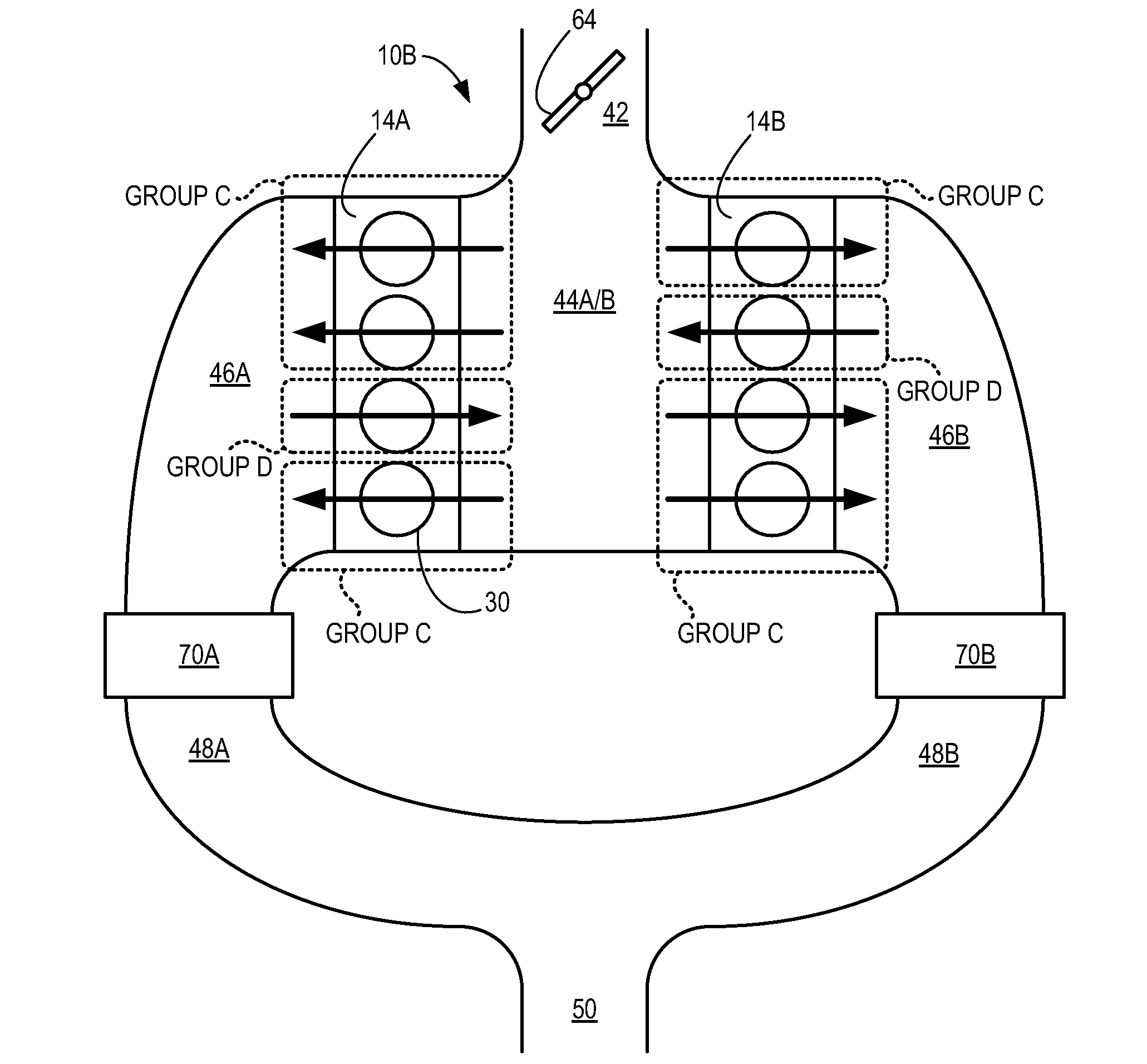
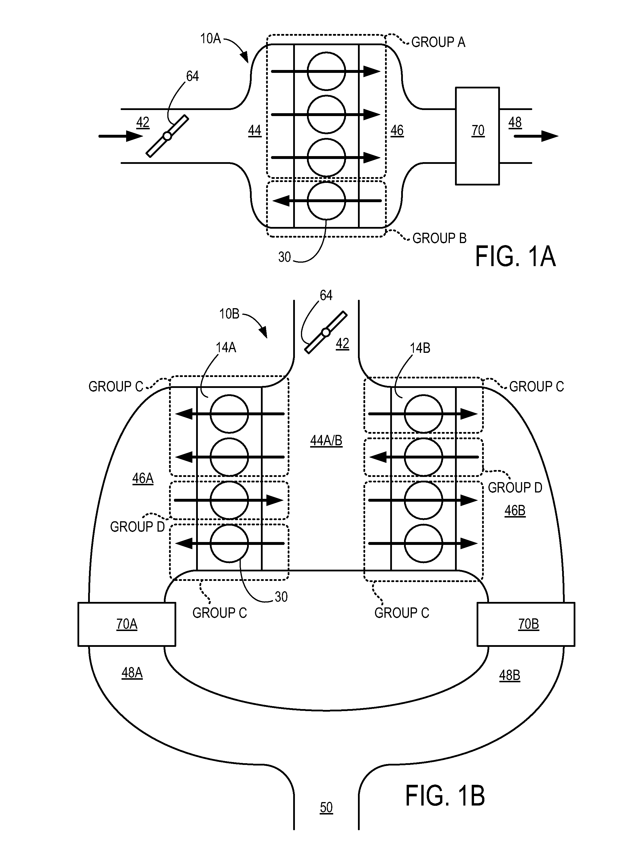
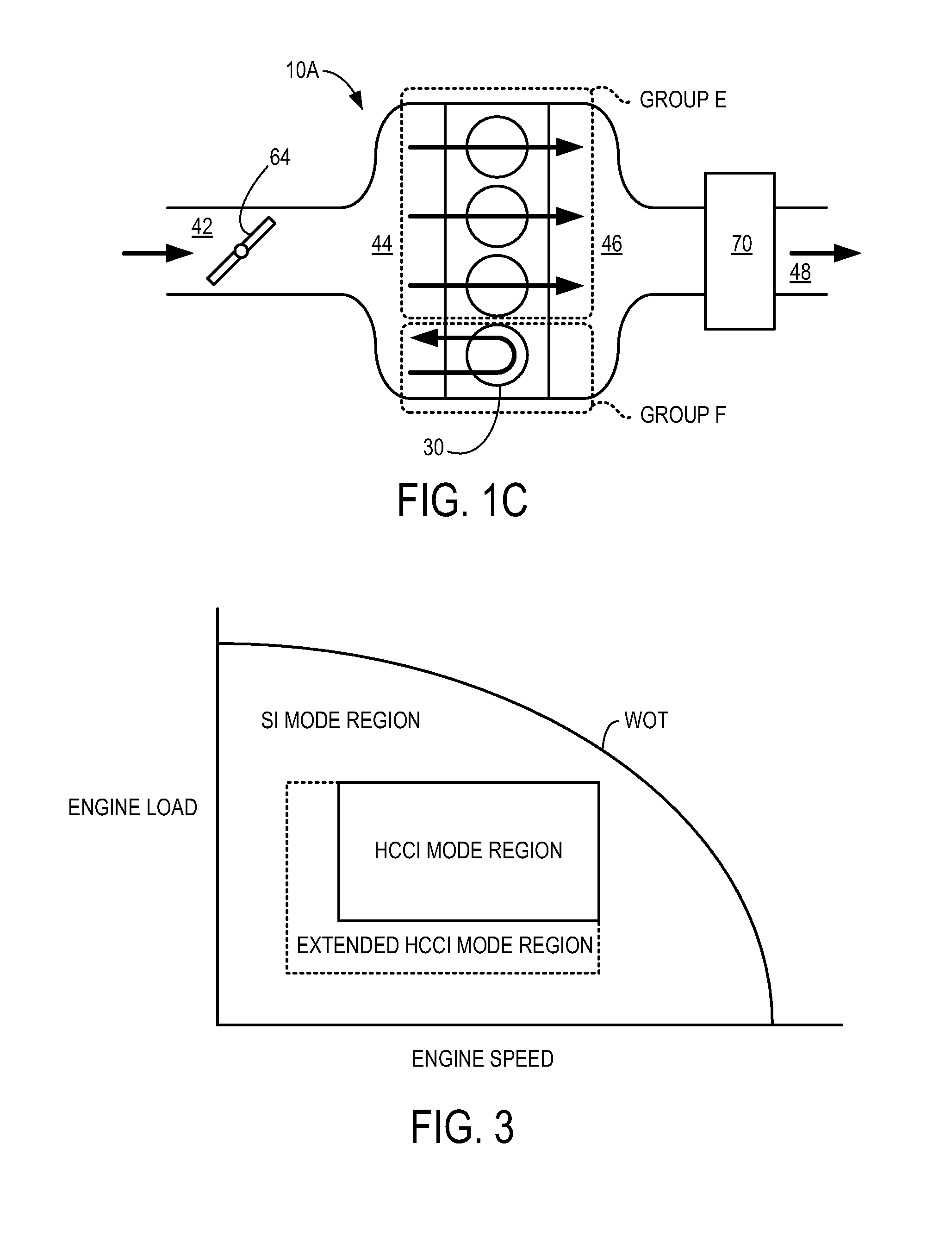
A method of operating an engine is provided. The engine includes at least one cylinder communicating with an intake manifold via an intake manifold valve and an exhaust manifold via an exhaust manifold valve, the cylinder including a piston arranged within the cylinder, wherein the piston is coupled to a crankshaft of the engine. The method comprises discontinuing combustion in the cylinder during a plurality of cycles of the engine; during the plurality of cycles, operating the exhaust manifold valve and the intake manifold valve to provide a net flow of gases from the exhaust manifold to the intake manifold via the cylinder and adjusting a torque signature provided to the crankshaft during each cycle by the piston responsive to an operating condition.

Description

BACKGROUND AND SUMMARY[0001]Some engines may be configured to perform what may be referred to as controlled auto-ignition (CAI), whereby a mixture including air and fuel is auto-ignited during a compression stroke of the cylinder's piston without necessarily requiring a spark or a pilot injection to initiate combustion. One particular type of controlled auto-ignition known as homogeneous charge compression ignition (HCCI) includes auto-ignition of a substantially homogenous mixture of air and fuel. HCCI may be used to achieve improved engine efficiency and reduced emissions, under some conditions. However, under other conditions, it may be difficult to achieve auto-ignition or to control the timing of auto-ignition. For example, during certain higher or lower engine torque or engine speed ranges, auto-ignition may be difficult to control resulting in misfire, engine knock, or pre-ignition.[0002]One approach to address this issue includes the use of charge temperature control to exte...

Claims


Application Information

Patent Timeline
Patent Type & Authority Applications(United States)
IPC IPC(8): F02D13/06
CPCF02B1/12F02B2075/125F02D13/0207F02D13/0219F02D13/0261F02D13/06F02D41/006F02D41/008F02D41/0087F02D41/3035F02M26/01F02M26/05F02M26/43Y02T10/12Y02T10/40
Inventor WINSTEAD, VINCENT J.
Owner FORD GLOBAL TECH LLC
Why Eureka
Try Eureka