Microwave scanning system and miniaturized microwave antenna

a scanning system and microwave technology, applied in the direction of resonant antennas, instruments, diagnostic recording/measuring, etc., can solve the problems of false diagnostics, difficult to use as a base for antenna arrays of several elements, and challenge the practical implementation of them

Inactive Publication Date: 2009-01-15
MCGILL UNIV
View PDF5 Cites 100 Cited by
  • Summary
  • Abstract
  • Description
  • Claims
  • Application Information

AI Technical Summary

Benefits of technology

[0011]Other objects, advantages and features of the present invention will become more apparent upon reading of the following non-

Problems solved by technology

X ray mammography, for example, exposes patients to low levels of ionizing radiation and often results in false diagnostic.
It is also uncomfortable as breast compression is often required to reduce image blurring and to create tissue uniformity.
However, these antennas have various drawbacks such as their large si

Method used


Image

  • Microwave scanning system and miniaturized microwave antenna
  • Microwave scanning system and miniaturized microwave antenna
  • Microwave scanning system and miniaturized microwave antenna

Examples


Embodiment Construction

[0029]The present invention is illustrated in further details by the following non-limiting examples.

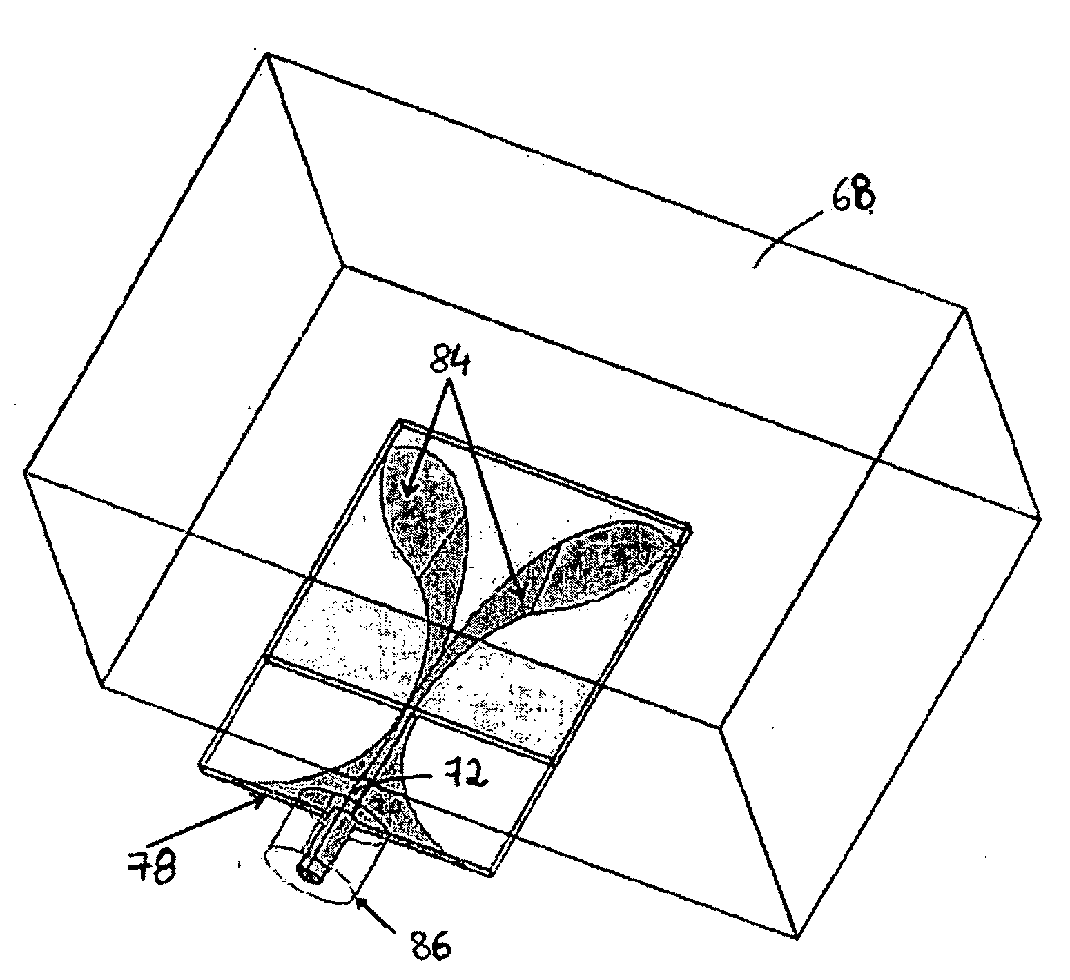
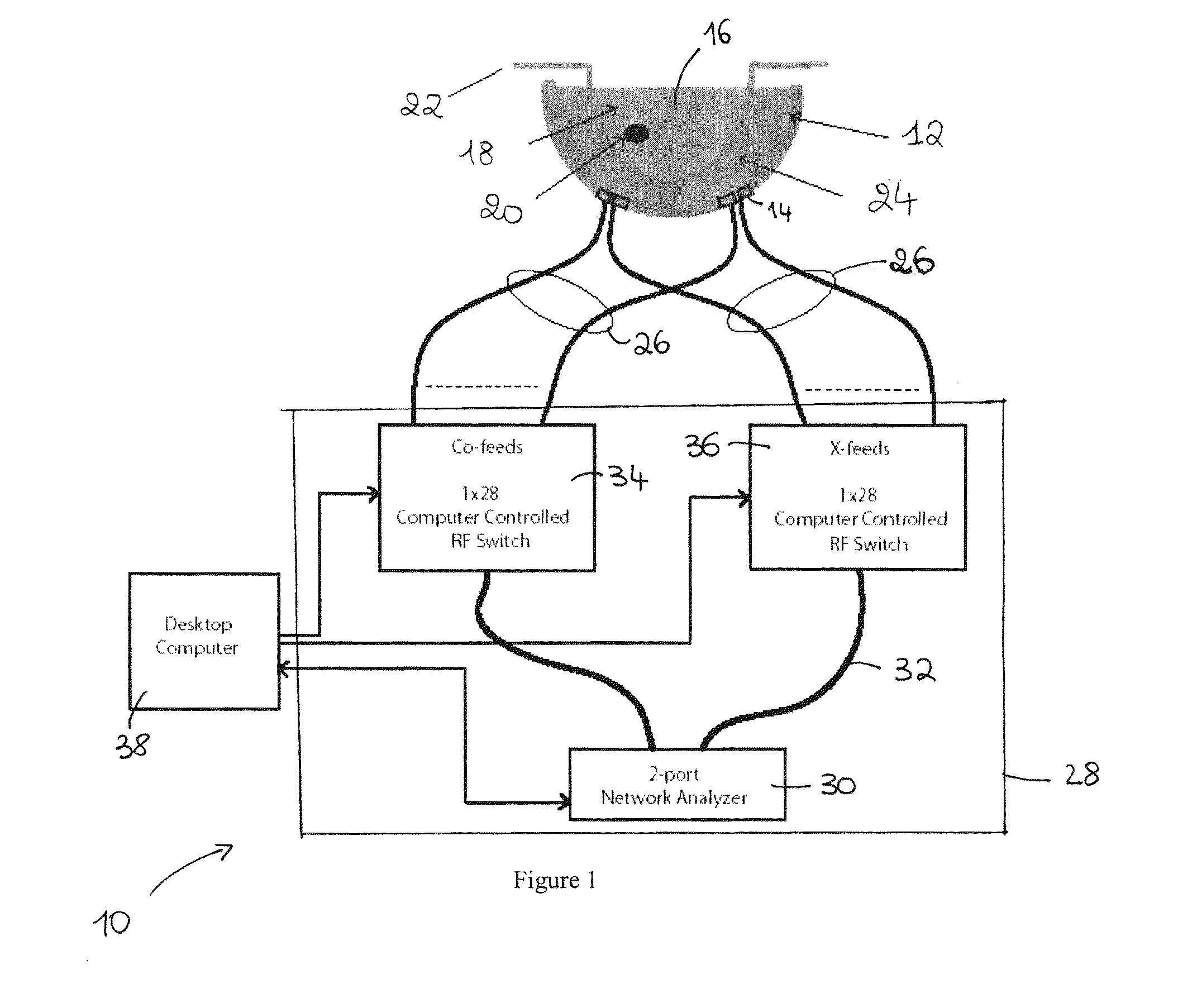
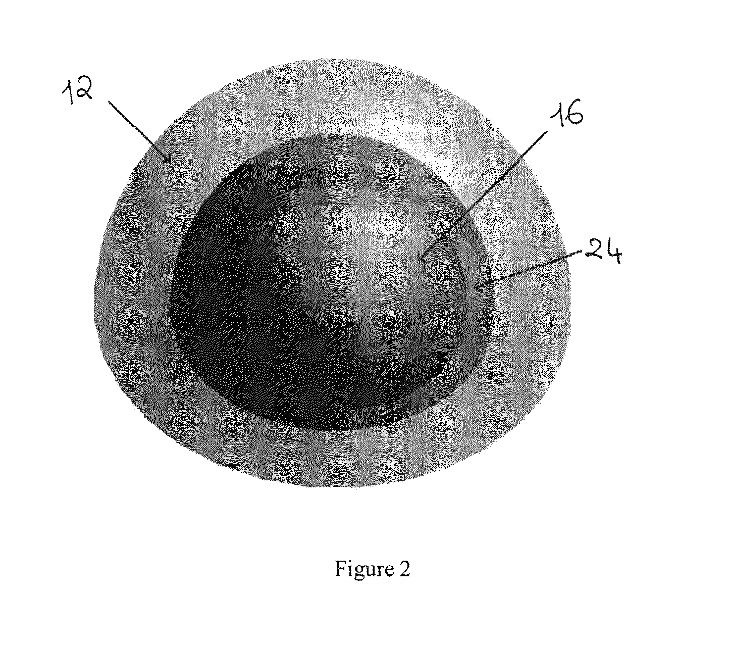
[0030]Referring to FIG. 1, and in accordance with an illustrative embodiment of the present invention, a system for breast cancer detection using microwave imaging, generally referred to using the reference numeral 10, will now be described. The system comprises a three-dimensional (3D) spherical dielectric support / radome 12 with through slits for inserting a plurality of scanning elements such as miniaturized antennas 14 that form the illustrated spherical 3D card scanner array. The support 12 as disclosed is illustratively an enclosure used to protect the antennas 14 from the effects of environmental exposure and comprises a hollow bowl like portion designed to fit optimally around the breast 16. In this regard, a diseased breast 16 may be modelled as a fat phantom 18 into which is incorporated a tumour phantom 20 and covered with a skin phantom 22. A liquid filled matching bag 24 ...


PUM


Abstract

A micro strip antenna comprising a planar substrate fabricated from a dielectric material and a pair of like elements arranged in mirror image on the planar substrate, each of the elements comprising a radiating portion comprising an elongate conductive strip of a constant thickness, the elongate conductive strip comprising first arcuate side edges mutually diverging between a narrow end and a wide end.
There is also disclosed a system for detecting the presence of a region having a first dielectric constant within a medium having a second dielectric constant different from the first dielectric constant, such as a tumour embedded in a fatty tissue. The system comprises a support fabricated from a material having a dielectric constant substantially the same as the second dielectric constant, a scanner array comprising a plurality of scanning elements embedded in the support, each of the scanning elements directing a series of microwave pulses into the medium and receiving backscatter returns resulting from the series of microwave pulses, and an analyzer coupled to each of the scanning elements, the analyzer collecting the backscatter returns and processing the backscatter returns to detect the region.

Description

CROSS REFERENCE TO RELATED APPLICATIONS[0001]The present application claims priority on U.S. Provisional Application Ser. No. 60 / 941,294 filed on Jun. 1, 2007 which is incorporated herein in its entirety by reference.FIELD OF THE INVENTION[0002]The present invention relates to a microwave scanning system and miniaturized microwave antenna. In particular, the present invention relates to a system implementing the miniaturized antenna for emitting microwaves and detecting backscatter which is subsequently analysed for detecting anomalies embedded in bodies.BACKGROUND OF THE INVENTION[0003]Microwave imaging systems are currently used in a variety of applications for detecting the presence and location of buried objects based on the reflections of microwave radiation. These systems typically illuminate a composite having specific dielectric properties with electromagnetic (EM) waves, which penetrate into the material where they interact with its interior. The waves are then reflected ba...

Claims


Application Information

Patent Timeline
IPC IPC(8): G01N22/00H01Q1/38
CPCA61B5/05A61B5/0507H01Q25/001H01Q1/42H01Q9/285A61B2562/02A61B5/4312A61B2562/046
Inventor POPOVIC, MILICAKANJ, HOUSSAM
Owner MCGILL UNIV
Why Eureka
Try Eureka