Method for driving surface emitting semiconductor laser, optical transmission module, and handheld electronic device

Active Publication Date: 2009-01-15
FUJIFILM BUSINESS INNOVATION CORP
View PDF4 Cites 7 Cited by
  • Summary
  • Abstract
  • Description
  • Claims
  • Application Information

AI Technical Summary

Benefits of technology

[0006]For devices, such as handheld devices, that are susceptible to electromagnetic noises, the use of an optical transmission module in which a VCSEL is used as a light source for signal transmission has been considered. A major technical difficulty therein is the reduction in power consumption of the VCSEL. One method for reducing power is to lower the threshold current of the VCSEL and reduce the driving current However, in general, if the threshold current is lowered, the internal resistance becomes high, and thus it becomes difficult to drive the VCSEL at a high speed.

Problems solved by technology

However, such a high resistant VCSEL has a higher resistance than a resistance of, for example, 50 ohms, that is typically used for a driving circuit or wiring and thus causes impedance mismatching.
A major technical difficulty therein is the reduction in power consumption of the VCSEL.
One method for reducing power is to lower the threshold current of the VCSEL and reduce the driving current However, in general, if the threshold current is lowered, the internal resistance becomes high, and thus it becomes difficult to drive the VCSEL at a high speed.

Method used


Image

  • Method for driving surface emitting semiconductor laser, optical transmission module, and handheld electronic device
  • Method for driving surface emitting semiconductor laser, optical transmission module, and handheld electronic device
  • Method for driving surface emitting semiconductor laser, optical transmission module, and handheld electronic device

Examples


Embodiment Construction

[0021]Referring to the accompanying drawings, exemplary embodiments for implementing the present invention will be now described.

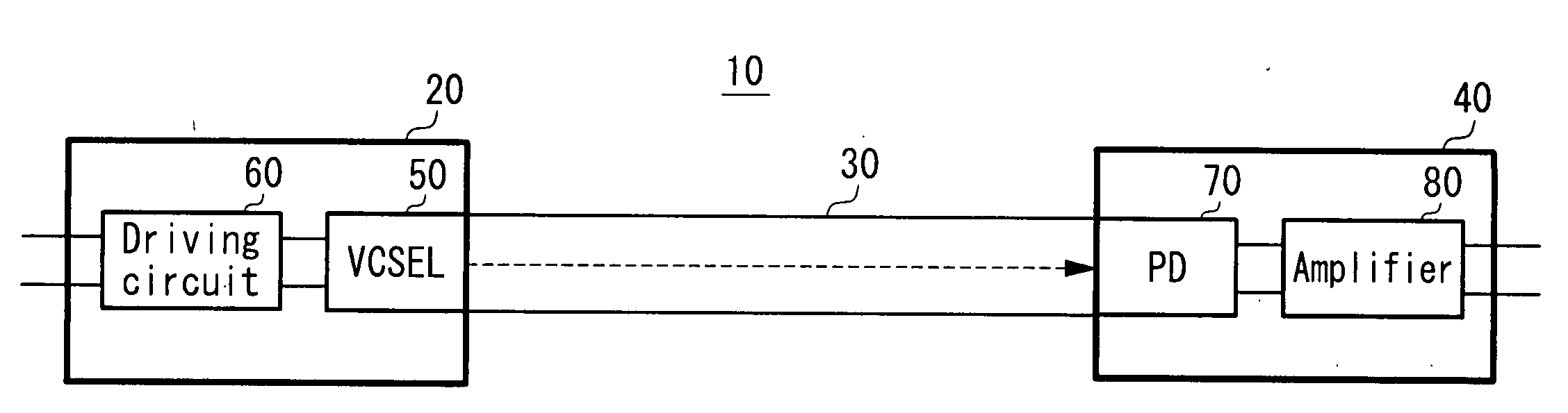
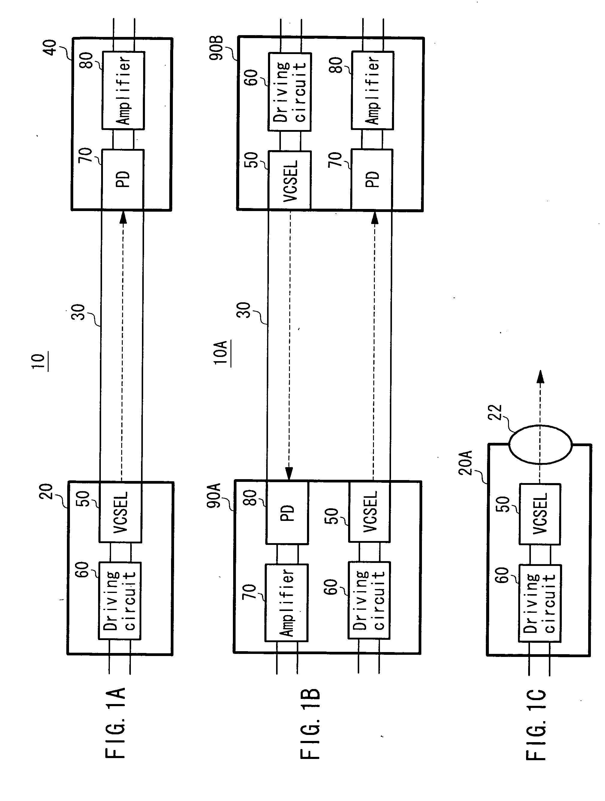
[0022]FIGS. 1A to 1C are schematic diagrams showing examples of a typical configuration of an optical transmission module according to an example of the present invention. As shown in FIG. 1A, an optical transmission module 10 is configured to include a light sending device 20 that sends an optical signal, an optical transmission medium 30 that transmits the sent optical signal, and a light receiving device 40 that receives the transmitted optical signal.

[0023]The light sending device 20 is capable of converting an electrical signal into an optical signal, and is configured to include a VCSEL 50, and a driving circuit 60 for driving the VCSEL 50. The VCSEL 50 emits laser light having a wavelength that corresponds to a transmission distance of the optical signal. In a case where the transmission distance is short, laser light of 850 nm, for example, may be ...


PUM


Abstract

Provided is a method for driving a surface emitting semiconductor laser including an active region that generates light, a resonator structure disposed such that it sandwiches the active region, and a driving electrode that provides power to the active region. The surface emitting semiconductor laser has an internal resistance defined by voltage and current applied to the driving electrode. The method includes applying a modulation signal to the driving electrode, in which the modulation signal has a current amplitude defined by a first current value and a second current value that is greater than the first current value. The modulation signal is in a negative gradient region in which the internal resistance decreases in contrast to the increase of the current.

Description

CROSS-REFERENCE TO RELATED APPLICATION[0001]This application is based on and claims priority under 35 USC 119 from Japanese Patent Application No. 2007-183875 filed Jul. 13, 2007.BACKGROUND[0002]1. Technical Field[0003]This invention relates to a method for driving a surface emitting semiconductor laser, an optical transmission module, and a handheld electronic device.[0004]2. Related Art[0005]For an optical transmission module that is modulated at a high speed in a gigahertz or higher frequency band, a surface emitting semiconductor laser (Vertical-Cavity Surface-Emitting Laser diode: hereinafter referred to as VCSEL) that is designed to have a small internal resistance is typically used. Some of single-mode VCSELs have an internal resistance of greater than 50 ohms; for example, an internal resistance of several hundred or several thousand ohms. However, such a high resistant VCSEL has a higher resistance than a resistance of, for example, 50 ohms, that is typically used for a dri...

Claims


Application Information

Patent Timeline
IPC IPC(8): H04B10/00H01S5/042H01S5/183
CPCH01S5/0427H04B10/504H01S5/18311H01S5/06812
Inventor UENO, OSAMUSAKAMOTO, AKIRASAKAI, KAZUHIRONAKAYAMA, HIDEOMURAKAMI, AKEMI
Owner FUJIFILM BUSINESS INNOVATION CORP
Why Eureka
Try Eureka