Medical Instrument

a technology for medical instruments and instruments, applied in the field of medical instruments, can solve the problems of medical instruments, medical instruments not being able to be operated with one hand by users, and the proximal end region of the outer shaft, and achieve the effect of being particularly cost-effectively manufactured

Active Publication Date: 2009-01-15
KARL STORZ GMBH & CO KG
View PDF8 Cites 5 Cited by
  • Summary
  • Abstract
  • Description
  • Claims
  • Application Information

AI Technical Summary

Benefits of technology

[0016]The result of configuring the proximal end region of the outer shaft with peripherally limited openings, through which the tappet elements extend, is that the proximal end region of the outer shaft is designed in one piece and extends over the torque transmission mechanics of the medical instrument, as a result of which the proximal end region of the outer shaft can be connected to an already present handle, without reconfiguring the latter. As a result, the medical instrument advantageously has minimal manufacturing costs.
[0042]In an axially adjacent arrangement of the two tappet elements, both tappet elements are arranged approximately on the same peripheral point of the shaft. The advantage of this measure is that the medical instrument can be manufactured particularly cost-effectively, since the inner shaft needs to have only one recess for both tappet elements. The openings of the outer shaft are hereby arranged peripherally offset by 180° and the control cams of the outer shaft are further designed such that they counterrotate and are likewise arranged offset by 180°.

Problems solved by technology

If it is planned to further develop such a medical instrument to the extent where, in addition to the outer shaft, it has an inner shaft inside the outer shaft which is rotatable about the longitudinal axis, the technical problem arises as to how corresponding torque transmission mechanics of the instrument could be designed which would allow relative rotation of the inner and outer shaft with simultaneous screwing of the outer shaft to the handle inside the handle.
With this configuration of the torque transmission mechanics there is the disadvantage, however, with this type of torque transmission of only minimal force transfer made to the inner shaft.
In this embodiment of the medical instrument it is a disadvantage, however, for both parts of the proximal end region of the outer shaft to have to be connected, such that it is rotationally fixed, to the handle.
This configuration of the medical instrument does however have the disadvantage of the medical instrument not being able to be operated with one hand by a user, since the actuator is arranged on the proximal side of the handle.

Method used


Image

  • Medical Instrument
  • Medical Instrument
  • Medical Instrument

Examples


Embodiment Construction

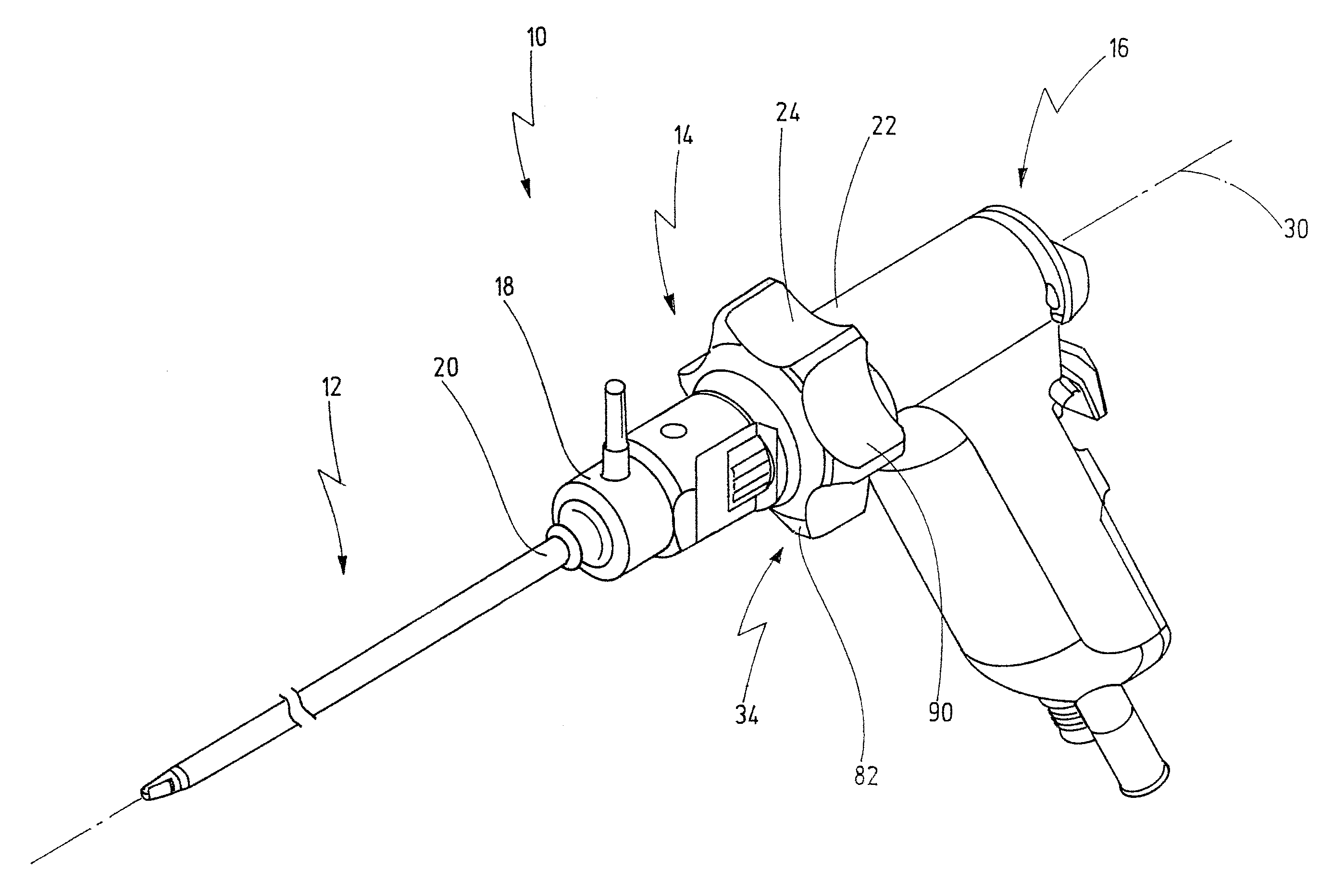
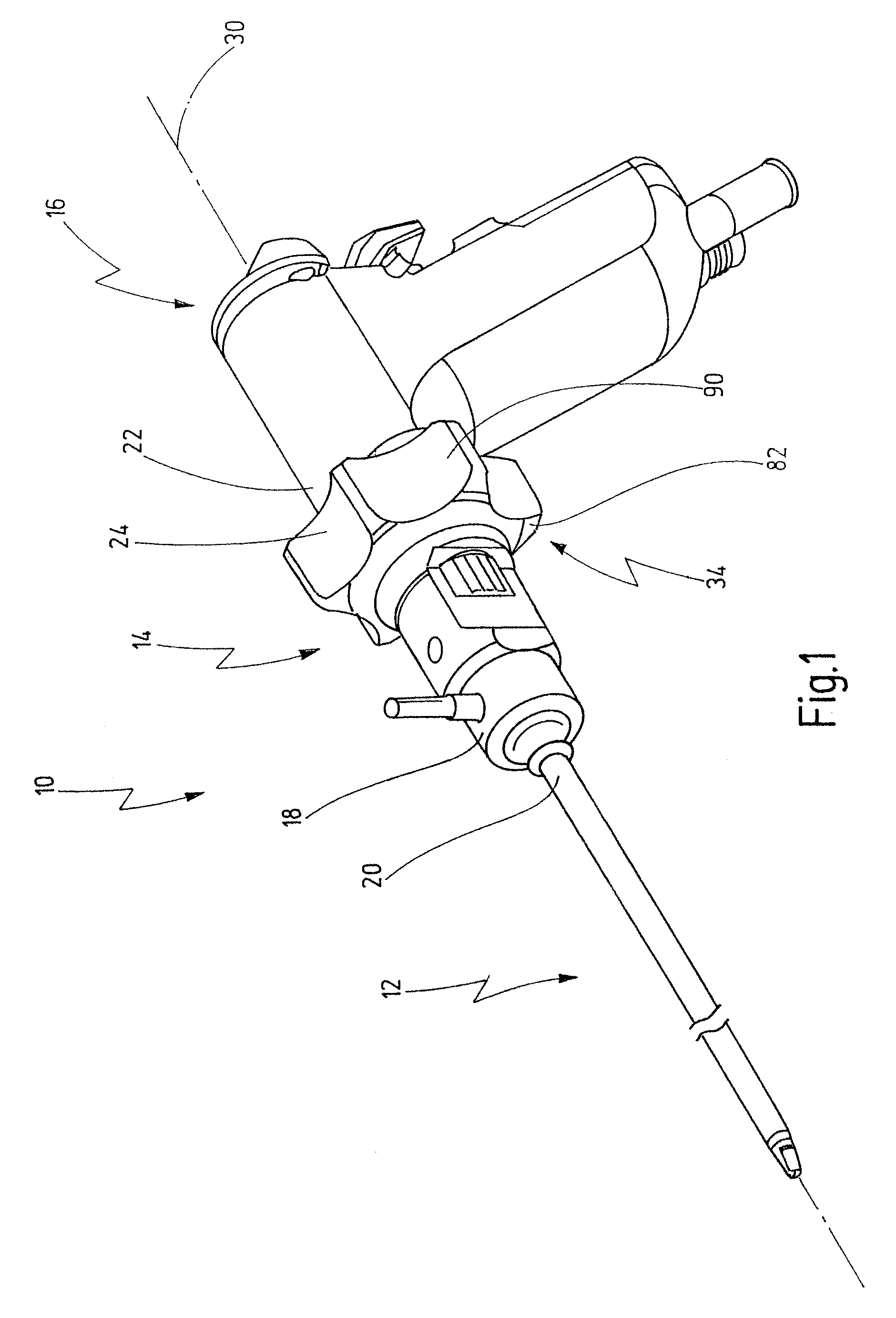
[0055]FIG. 1 illustrates a medical instrument provided with the general reference numeral 10. Further details of the medical instrument 10 are shown in FIGS. 2 to 9C.

[0056]The medical instrument 10 is used, for example, in the field of minimally invasive surgery during a laparoscopic procedure for atrophying sectioned tissue of a patient or for removing diseased tissue of the patient.

[0057]The medical instrument 10 has a shaft 12, a coupling element 14 and a handle 16. A distal end region 18 of the coupling element 14 is connected to a proximal end region 20 of the shaft 12 and a distal end region 22 of the handle 16 is connected to a proximal end region 24 of the coupling element 14.

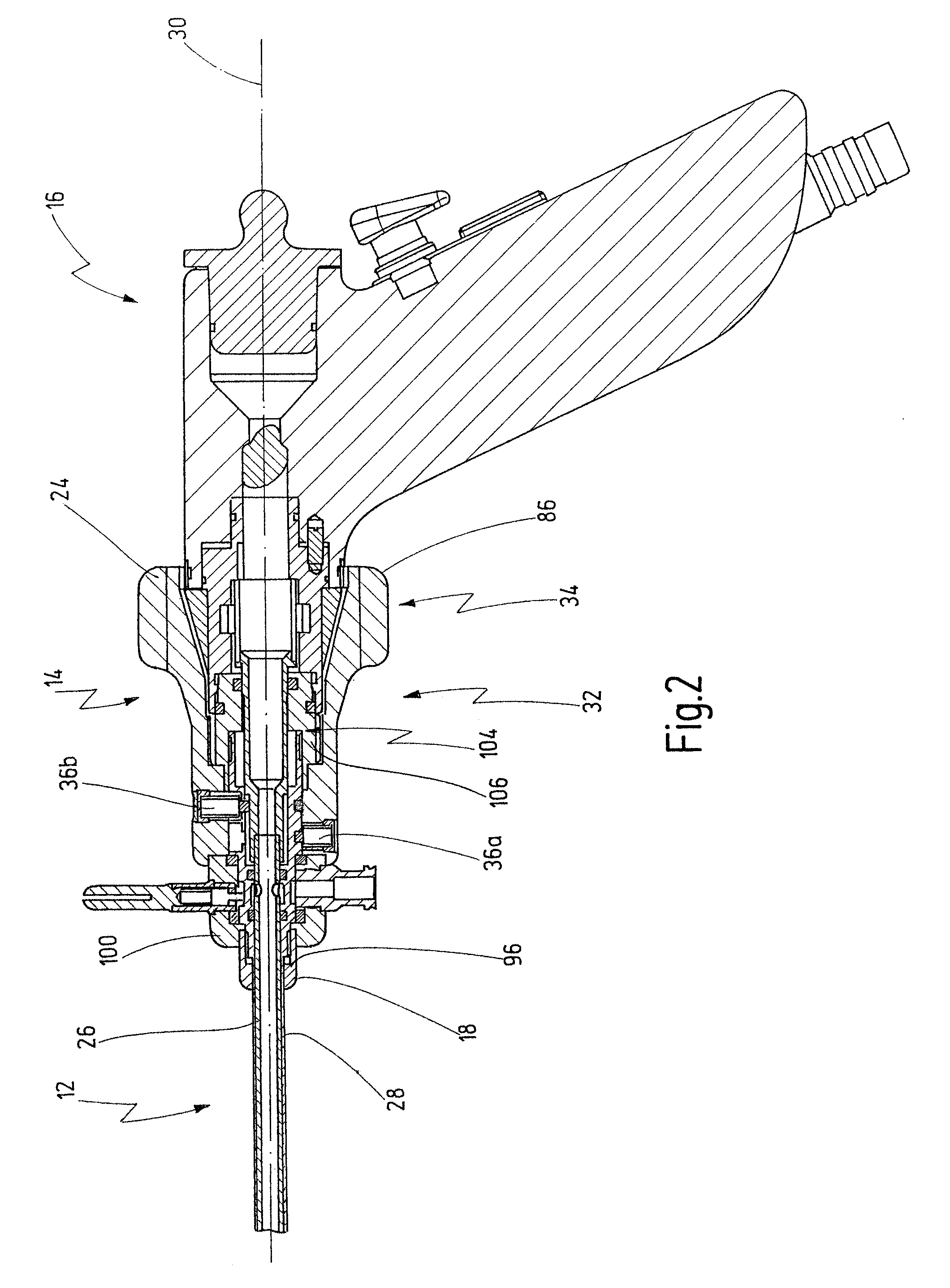
[0058]As shown in FIG. 2, the shaft 12 is designed in two parts, and it has a respectively tubular inner shaft 26 and outer shaft 28. The inner shaft 26 is housed in the outer shaft 28 and designed such that it can rotate relative to the outer shaft 28 about a longitudinal axis 30 of the medical instrum...


PUM


Abstract

A medical instrument has a shaft. The shaft has an outer shaft and an inner shaft. The outer shaft encloses the inner shaft. The medical instrument further has an actuator for rotating the inner shaft about a longitudinal axis relative to the outer shaft, arranged at a proximal end region of the shaft. The medical instrument has at least two tappet elements for transferring a rotary movement of the actuator to the inner shaft, which are engaged interchangeably with the inner shaft for transferring the rotary movement of the actuator to the inner shaft. The tappet elements reach through peripherally limited openings in a proximal end region of the outer shaft, which openings are offset with respect to one another in the longitudinal direction.

Description

CROSS REFERENCE TO RELATED APPLICATION[0001]The present application claims priority of German patent application No. 10 2007 034 577.3 filed on Jul. 13, 2007.BACKGROUND OF THE INVENTION[0002]The invention generally relates to medical instruments. More specifically, the invention relates to medical instruments, having a shaft which has an outer shaft and an inner shaft, wherein the outer shaft encloses the inner shaft, and wherein the inner shaft is rotatable with respect to the outer shaft.[0003]Medical instruments of the type initially described are used, for example, in minimally invasive surgery during a laparoscopic procedure to remove diseased tissue or also to atrophy previously sectioned tissue. For this purpose, a distal end region of the shaft of the medical instrument is inserted into a body cavity of a patient, on which corresponding gripping instruments, electrodes or the like are arranged. The shaft of the medical instrument is usually designed in two parts and has an i...

Claims


Application Information

Patent Timeline
Patent Type & Authority Applications(United States)
IPC IPC(8): A61B17/32
CPCA61B17/32002A61B17/32053A61B18/1482A61B2217/007A61B2017/320028A61B2017/320775A61B2217/005A61B2017/2913
Inventor BACHER, UWE
Owner KARL STORZ GMBH & CO KG
Why Eureka
Try Eureka