

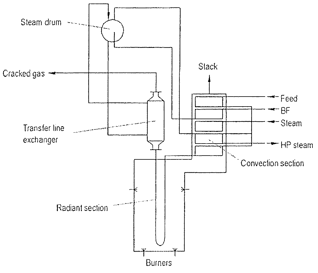
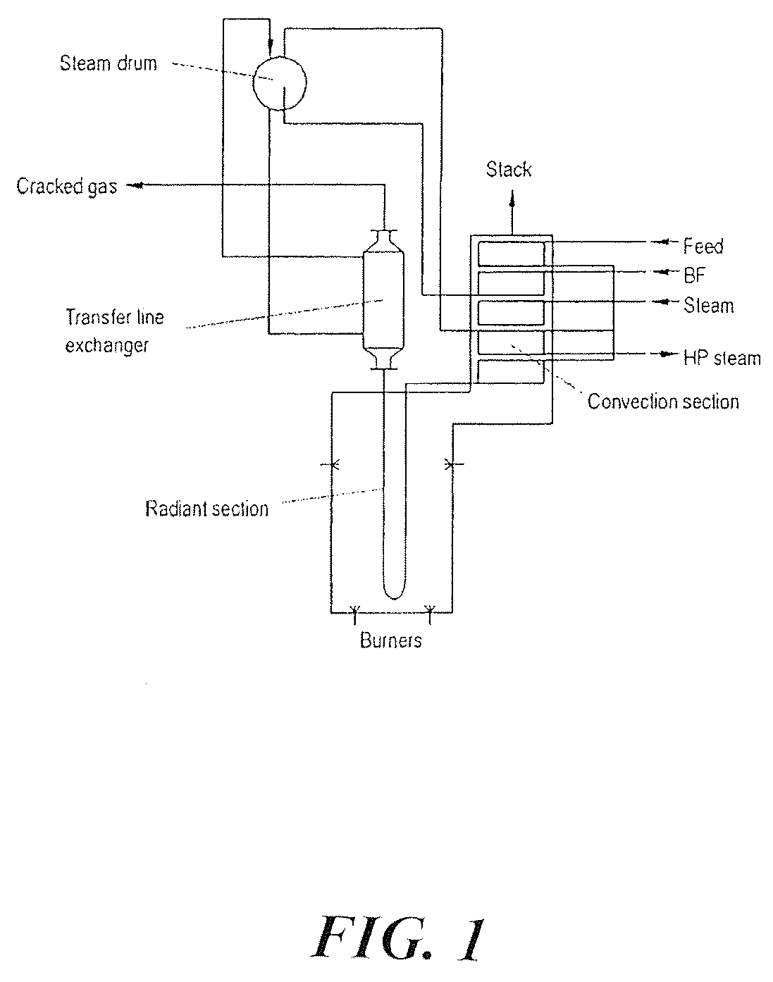
Ethylene furnace radiant coil decoking method
a technology of ethylene furnace and radiant coil, which is applied in the direction of furnaces, hydrocarbon oil treatment products, lighting and heating apparatus, etc., can solve the problems of reducing the heat transfer and cracking efficiency of the cracking process, increasing the coil pressure drop, and requiring furnace coil decoking, so as to avoid or reduce the damage of the radiant coil, the effect of rapid decoking process
- Summary
- Abstract
- Description
- Claims
- Application Information
AI Technical Summary
Benefits of technology
Problems solved by technology
Method used
Image

Examples
example 1
[0027]Step 1. When the furnace is ready for decoking, the fuel heat duty controller is cascaded to the average COT controller. Dilution steam flow is provided to the furnace at a rate such that the flow velocity in the tube is 100 to 125 m / sec. The average COT set point should be ramped to about 40° C. to 60° C. below the final decoking temperature. The fuel firing rate is adjusted by the COT controller as necessary to maintain the COT at the desired set point. The steam flow and average COT temperature are preferably maintained as described above for about one hour.
[0028]Step 2. The fuel firing control is placed in heat duty control (i.e. QIC) by breaking the fuel heat duty controller cascade to the average COT controller. The fired heat duty is maintained constant. The steam flow rate is maintained at the same level as used in Step 1. Decoking air is added while observing the COTs for each coil. If the air flow rate is too low to obtain a reading from the flow meter, the decoking ...
example 2
[0032]An exemplary detailed decoking procedure for a particular four coil furnace is provided in the attached Process Description and summarized in Table 1.
[0033]It should be understood that the exemplary processes described above are not intended to limit the invention in any way and are provided only to describe specific embodiments of the method of the invention. While specific embodiments of the present invention have been described above, one skilled in the art will recognize that numerous variations or changes may be made to the process described above without departing from the scope of the invention as recited in the appended claims.
TABLE 1Sample Decoke ProcedureMass flowMass flowrate per furnacerate per coilDurationsteamairtotalsteamairtotalStephoursCOTkg / hkg / hkg / hkg / hkg / hkg / h11AVERAGE1200001200020000200083021.5MAXIMUM12000MAXIMUMMAXIMUM2000MAXIMUMMAXIMUM850190013900317231731.5 to 2.5MAXIMUM12000MINIMUMMAXIMUM2000MINIMUMMAXIMUM875FINAL13900FINAL2317960160MAXIMUMMAXIMUM19003...
PUM
| Property | Measurement | Unit |
|---|---|---|
| Temperature | aaaaa | aaaaa |
| Temperature | aaaaa | aaaaa |
| Temperature | aaaaa | aaaaa |
Abstract
Description
Claims
Application Information