Exhaust pipe support

a technology for exhaust pipes and supports, applied in the direction of machine supports, shock absorbers, machines/engines, etc., can solve the problems of deterioration of damping effect and -shaped exhaust pipe supports, and achieve the effects of improving static spring constant, and increasing the volume of the second reinforcement rib

Active Publication Date: 2009-01-22
SUMITOMO RIKO CO LTD
View PDF8 Cites 14 Cited by
  • Summary
  • Abstract
  • Description
  • Claims
  • Application Information

AI Technical Summary

Benefits of technology

[0011]The present invention has been made in the light of the situations described above. It is therefore an object of the invention to provide an improved structure of an exhaust pipe support capable of advantageously increasing vibration damping effect in a high frequency range without deteriorating vibration damping effect in a middle to lower frequency range.

Problems solved by technology

However, in such a conventional exhaust pipe support, when large tensile stress and compression stress is applied to the pair of arm portions in the vertical direction due to input vibration, a phenomenon of surging occurs by which the pair of arm portions vibrates in both directions perpendicular to the vertical and axial directions of the ring-shaped elastic body composing the exhaust pipe support, especially in antiphase.
This may cause the problem of deterioration in damping effect.
However, inventors of the present application examined vibration damping performance of such a conventional θ-shaped exhaust pipe support in various ways, and found that such a θ-shaped exhaust pipe support has a problem related to vibration damping that is not observed in the conventional so-called O-shaped exhaust pipe support not having a center connecting part.

Method used


Image

  • Exhaust pipe support
  • Exhaust pipe support
  • Exhaust pipe support

Examples


Embodiment Construction

[0044]To further clarify the present invention, there will be described in detail embodiments of the invention with reference to the accompanying drawings.

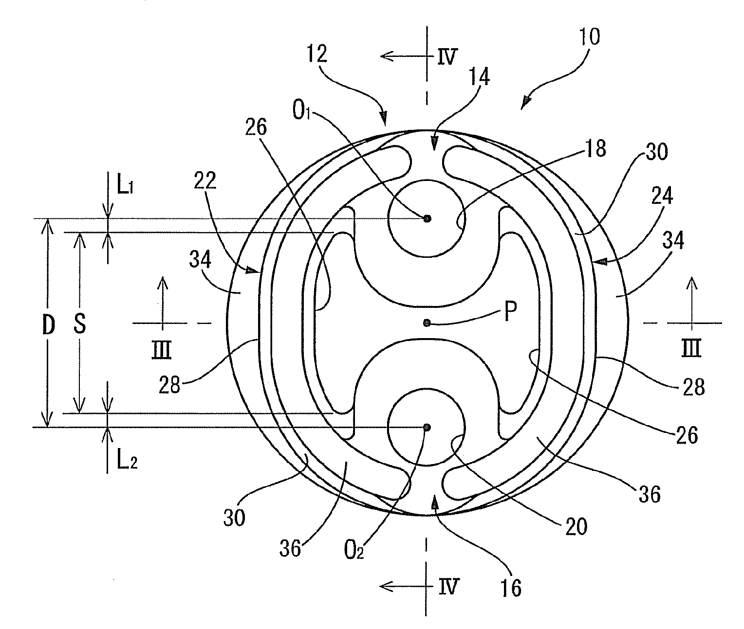
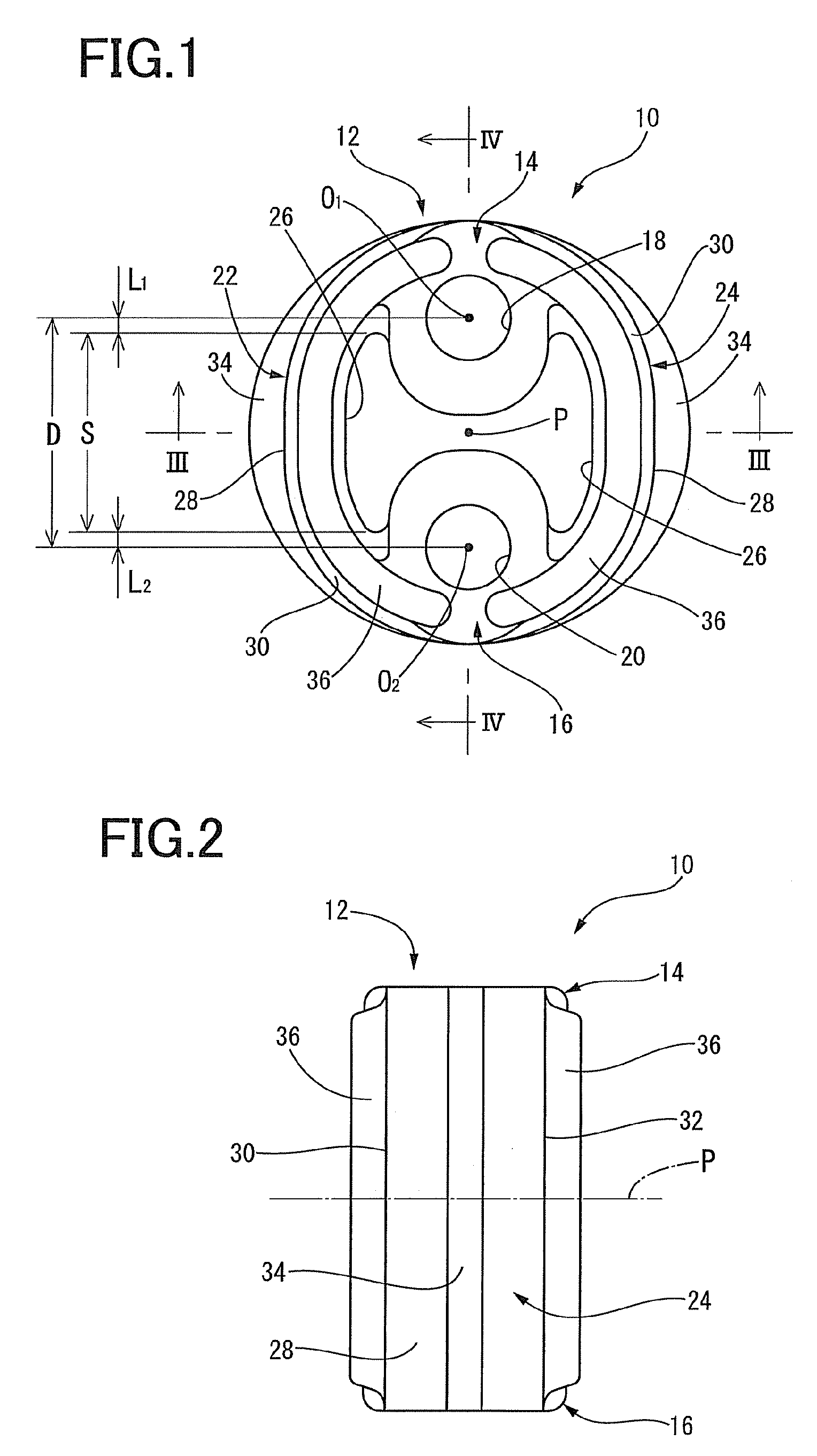
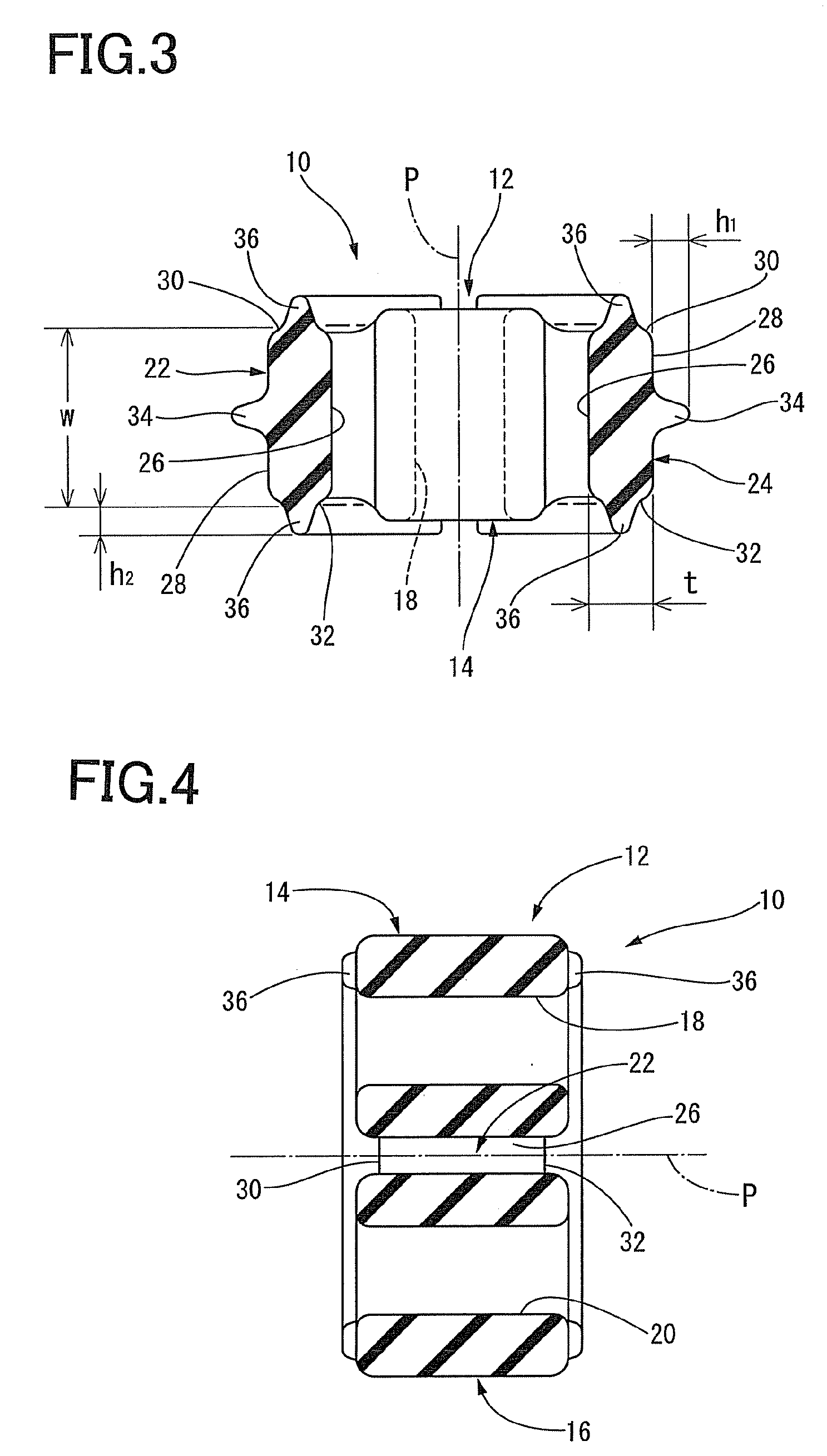
[0045]Referring first to FIG. 1, as one embodiment of an exhaust pipe support having a structure according to the present invention, there is shown a front view of a muffler support retaining an exhaust pipe of an automobile to a vehicle body. FIG. 2 is a side view of the muffler support. FIG. 3 and FIG. 4 show a horizontal sectional view and a vertical sectional view respectively in the axial direction of the muffler support. As is apparent from these views, a muffler support 10 of the present embodiment has an elastic body 12 formed of rubber elastic material. The elastic body 12 has an oval ring or a cylindrical shape.

[0046]As shown in FIG. 1, an upper attachment portion 14 and a lower attachment portion 16 is integrally provided in the elastic body 12 with a predetermined distance therebetween (spaced apart from each other) in...


PUM

PropertyMeasurementUnit
frequencyaaaaaaaaaa
frequencyaaaaaaaaaa
frequencyaaaaaaaaaa

Abstract

An exhaust pipe support including an elastic body having a ring shape, the elastic body comprising: an upper attachment portion having an upper attachment hole; a lower attachment portion having a lower attachment hole; and a pair of arm portions mutually connecting the upper and lower attachment portion. A first reinforcement rib is integrally formed on each outer circumferential surface of the arm portions. An upper end thereof is located at a higher position than a connecting position of an inner circumferential surface of the arm portion and the upper attachment portion and at a higher position than the center of the upper attachment hole, while a lower end thereof is located at a lower position than a connecting position of the inner circumferential surface of the arm portion and the lower attachment portion and at a lower position than the center of the lower attachment hole.

Description

[0001]The present application is based on Japanese Patent Application No. 2007-185144 filed on Jul. 17, 2007, the contents of which are incorporated herein by reference.BACKGROUND OF THE INVENTION[0002]1. Field of the Invention[0003]The present invention relates to an exhaust pipe support, and in particular to an improved structure of an exhaust pipe support that is suitably used for supporting an exhaust pipe of a vehicle such as automobile to the vehicle body in a vibration damping fashion.[0004]2. Discussion of Related Art[0005]Generally, an exhaust pipe of engine (internal combustion engine) in a vehicle such as automobile is connected to the engine at a front end thereof which is positioned at a front side in the frontward and backward direction of the vehicle. At the middle and rearward thereof, the exhaust pipe is elastically suspended and supported to the vehicle body via an exhaust pipe support made of a predetermined elastic supporting member, which is a so-called muffler ...

Claims


Application Information

Patent Timeline
Patent Type & Authority Applications(United States)
IPC IPC(8): F16M13/00F01N13/18F01N13/08
CPCB60K13/04F01N13/1822F16L55/035F16F1/376F16F1/46F01N2530/22
Inventor MIYATA, HIROKINANNO, TAKANOBU
Owner SUMITOMO RIKO CO LTD
Why Eureka
Try Eureka