Variable capacitor

Active Publication Date: 2004-12-23
MURATA MFG CO LTD
View PDF4 Cites 0 Cited by
  • Summary
  • Abstract
  • Description
  • Claims
  • Application Information

AI Technical Summary

Problems solved by technology

Unfortunately, in such a capacitor, the capacitances C11 and C12, which are connected in series, disadvantageously increase a resistance (ESR) resulting from a resistive component induced in the stator electrode.
As a result, the

Method used


Image

  • Variable capacitor
  • Variable capacitor
  • Variable capacitor

Examples


Embodiment Construction

[0039] A variable capacitor according to the present invention is not limited to the above-described preferred embodiments. Numerous and various modifications can be made without departing from the spirit of the present invention.

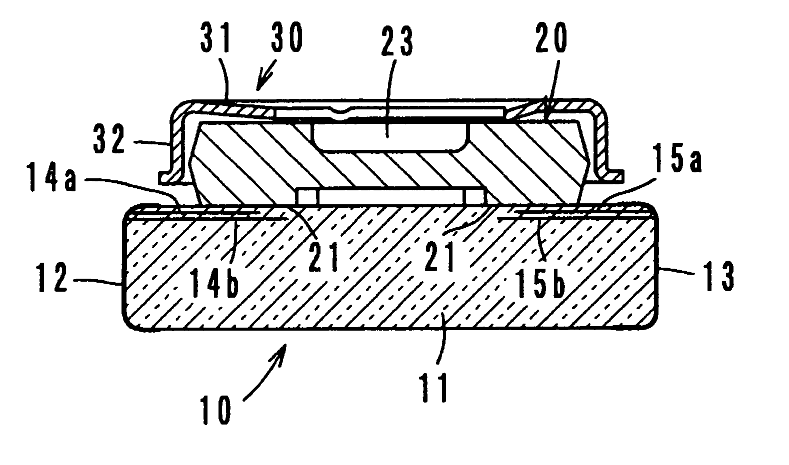
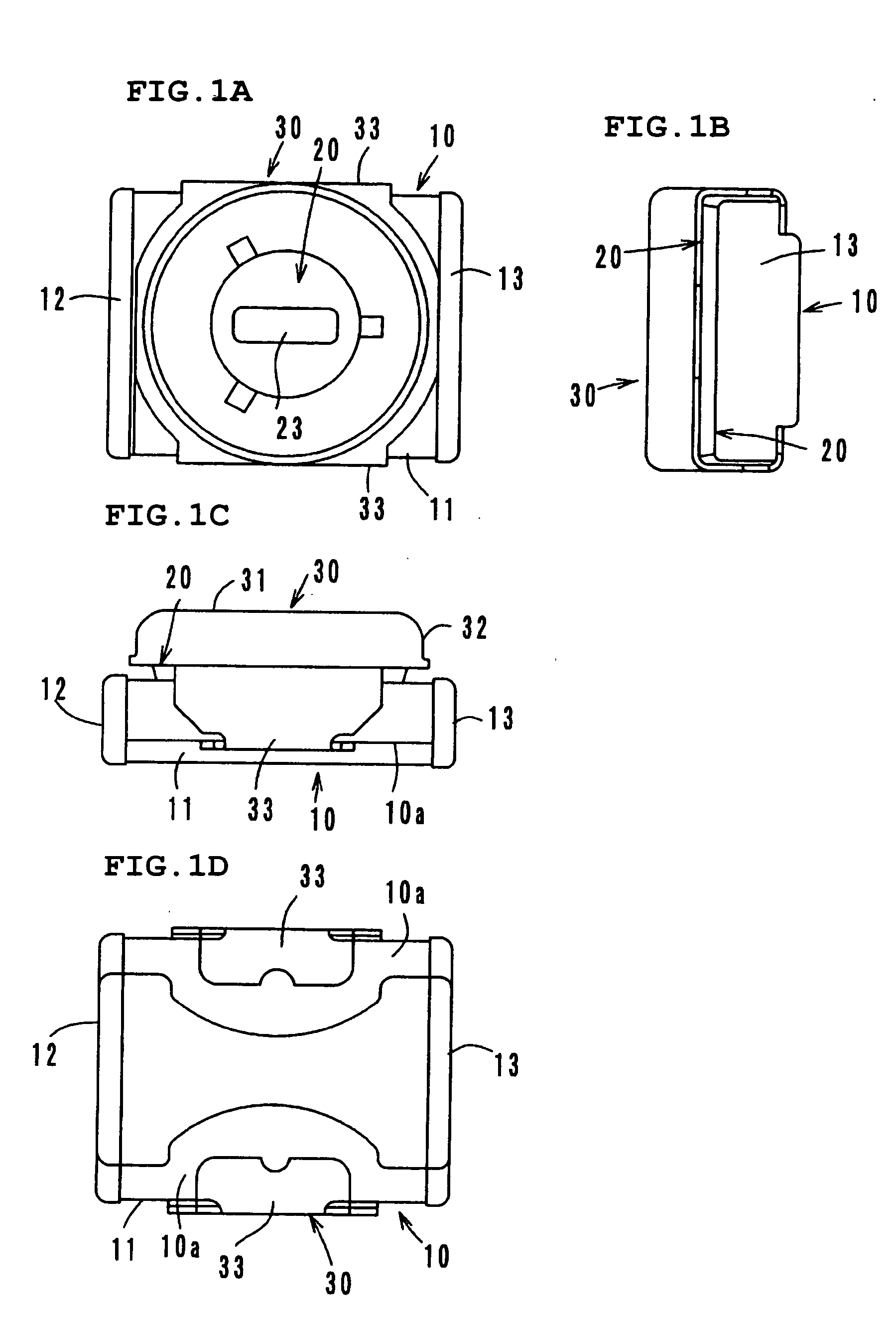
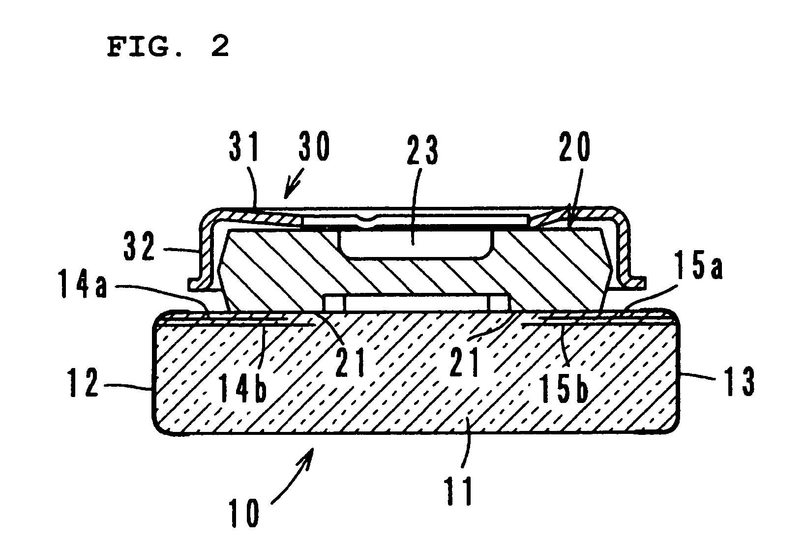
[0040] For example, the structures and shapes of the stator, the rotor, and the cover can be determined freely. In particular, the shapes of the stator electrode and the rotor electrode, and the number of layers of the stator electrode can be determined freely. In addition to the stator electrodes, other elements may be incorporated in the substrate of the stator.

[0041] While the present invention has been described with respect to preferred embodiments, it will be apparent to those skilled in the art that the disclosed invention may be modified in numerous ways and may assume many embodiments other than those specifically set out and described above. Accordingly, it is intended by the appended claims to cover all modifications of the invention which fall w...


PUM


Abstract

A variable capacitor includes a stator and a rotor rotatably supported by a cover relative to the stator. The stator includes a first stator electrode of two or more layers and a second stator electrode of two or more layers in the interior of a dielectric substrate. The first stator electrode is connected to a first external electrode and the second stator electrode is connected to a second external electrode. The rotor includes a rotor electrode of two pieces opposing the stator electrodes, and capacitances are defined in the areas of overlap of the rotor electrode and stator electrodes. The capacitances are adjustable to extremely small levels.

Description

[0001] 1. Field of the Invention[0002] The present invention relates to a variable capacitor and, in particular, to a variable capacitor having a stator and a rotor that is rotatably supported relative to the stator, in which rotation of the rotor changes the area of overlap of a stator electrode and a rotor electrode so as to change the capacitance.[0003] 2. Description of the Related Art[0004] Variable capacitors in which rotation of a rotor having a rotor electrode changes the area of overlap of a stator electrode in a stator and the rotor electrode to change their capacitance are disclosed in Japanese Unexamined Patent Application Publication No.10-233338 (hereinafter referred to as Patent Document 1) and U.S. Pat. No. 4,112,480 (hereinafter referred to as Patent Document 2).[0005] FIG. 8 shows the equivalent circuit of the variable capacitor disclosed in Patent Document 1. Rotation of a single rotor changes two capacitances C11 and C12. The variable capacitor is designed so tha...

Claims


Application Information

Patent Timeline
IPC IPC(8): H01G5/06H01G5/00
CPCH01G5/06
Inventor KATO, WATARU
Owner MURATA MFG CO LTD
Why Eureka
Try Eureka