Motor drive apparatus and its inspection method

a technology of motor drive and inspection method, which is applied in the direction of windings, instruments, transportation and packaging, etc., can solve the problems achieve the effect of worsening inspection workability

Inactive Publication Date: 2009-01-22
HITACHI ASTEMO LTD
View PDF3 Cites 42 Cited by
  • Summary
  • Abstract
  • Description
  • Claims
  • Application Information

AI Technical Summary

Benefits of technology

[0003]However, even if the above-mentioned countermeasure is taken, there is the following problem. That is, when a current supply test of the control board is carried out under the state where the motor components have been attached to the control board (the integrated housing), the motor is drivingly rotated so that an inspection workability is worsened. Therefore, it is hoped a motor drive apparatus capable of carrying out the inspection of control board before the assembly (attaching) of motor components and also capable of ensuring an accuracy of attaching position of the motor after the assembly of the motor components will be realized.

Problems solved by technology

However, even if the above-mentioned countermeasure is taken, there is the following problem.
That is, when a current supply test of the control board is carried out under the state where the motor components have been attached to the control board (the integrated housing), the motor is drivingly rotated so that an inspection workability is worsened.

Method used


Image

  • Motor drive apparatus and its inspection method
  • Motor drive apparatus and its inspection method
  • Motor drive apparatus and its inspection method

Examples


first embodiment

[0027][System Configuration of Electric Power-Steering Apparatus]

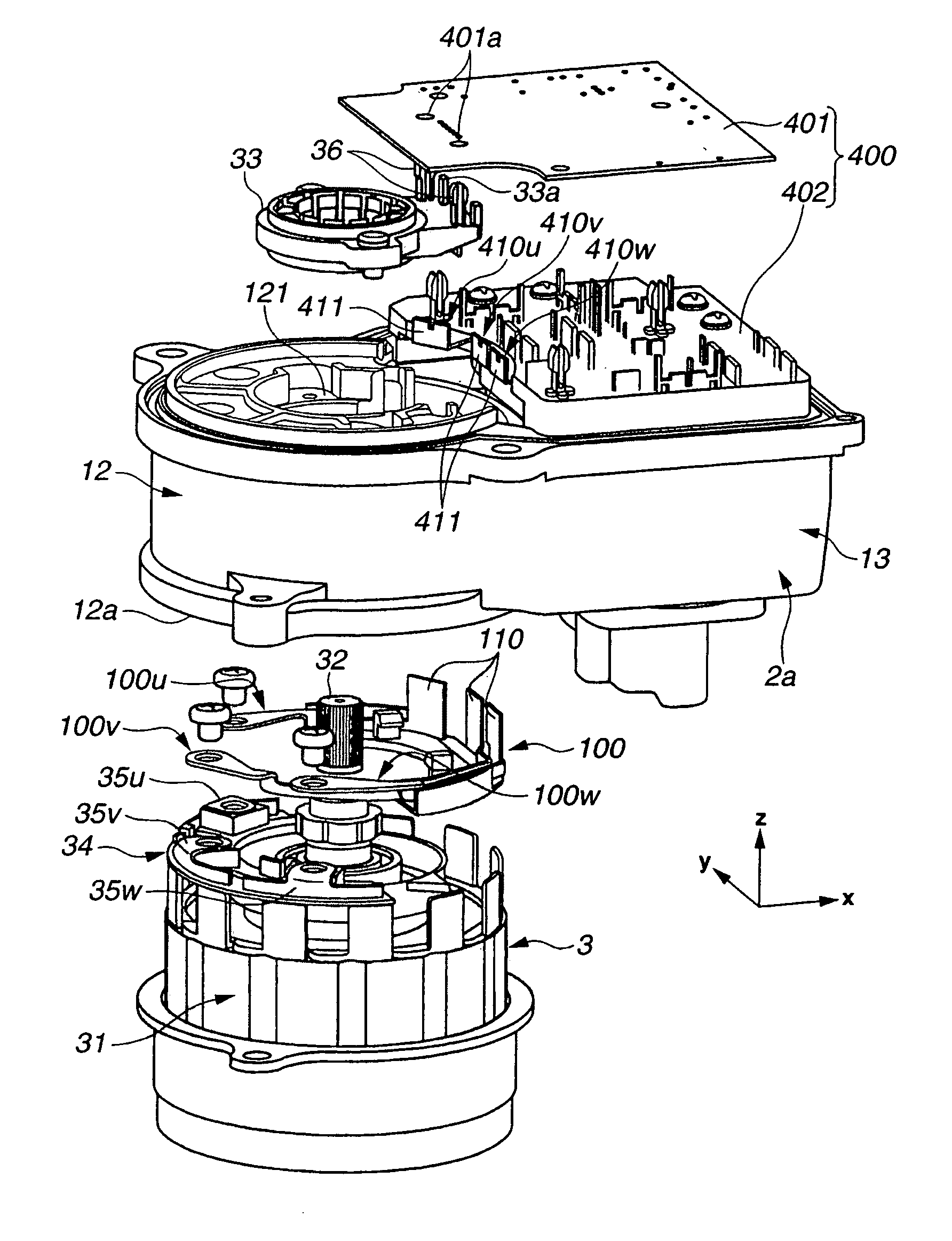
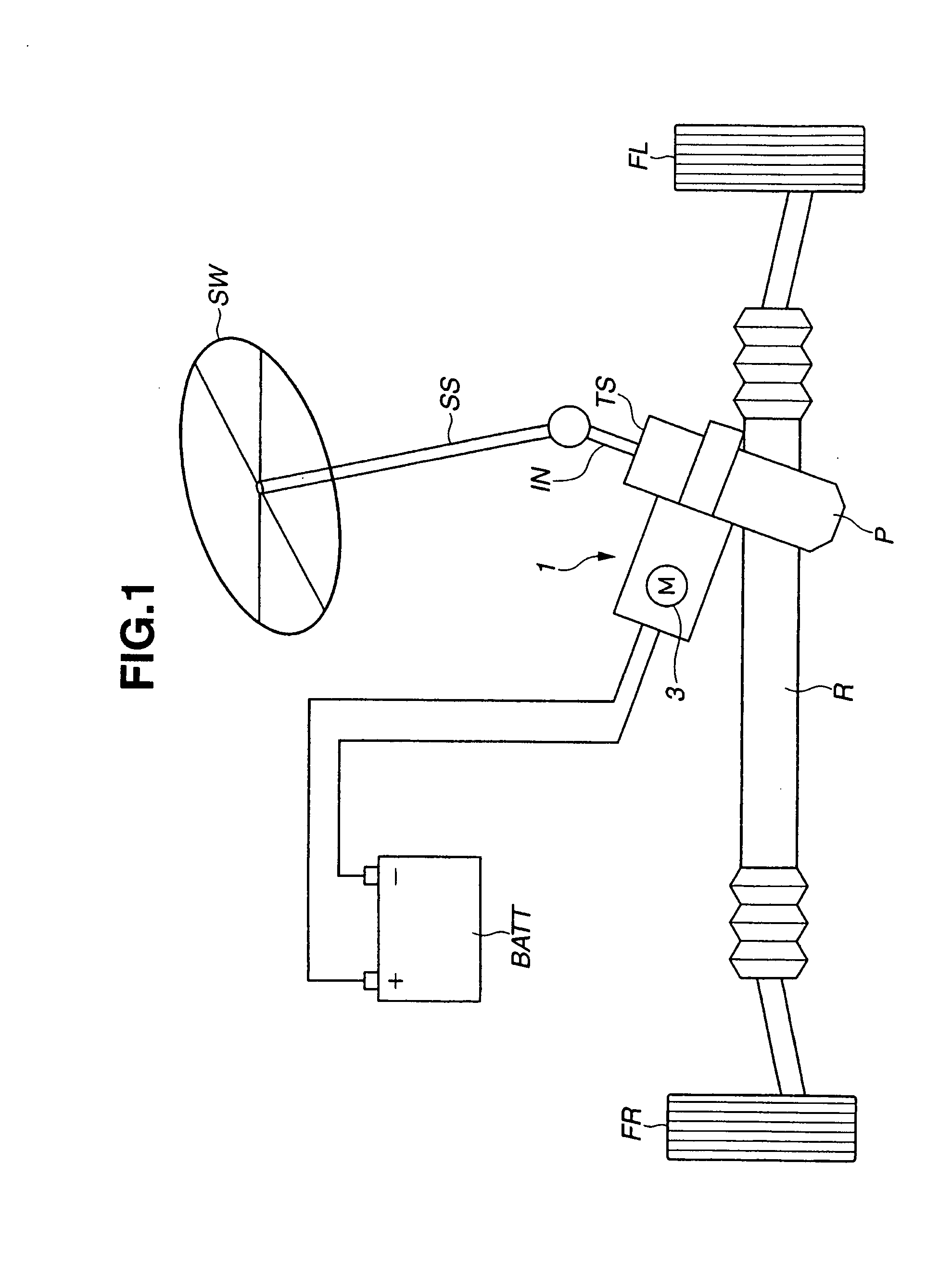
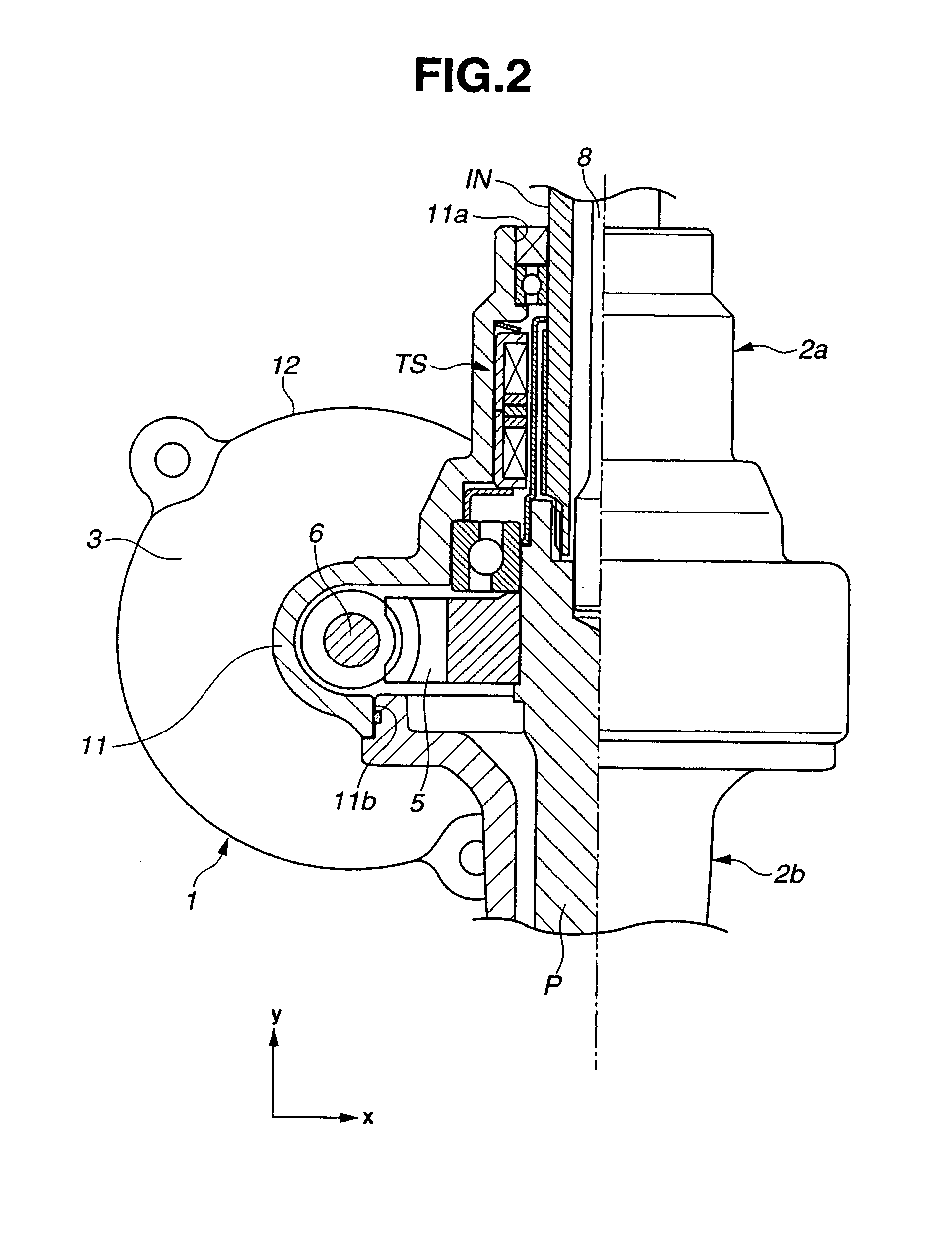
[0028]A first embodiment according to the present invention will now be explained. FIG. 1 is a schematic system configuration view of an electric power-steering apparatus employing a motor control apparatus (motor drive apparatus) 1 according to the first embodiment. The electric power-steering apparatus includes the motor control apparatus 1, a steering wheel SW, a steering shaft SS, a torque sensor TS, an input shaft IN, rack and pinion (steering mechanism: rack R, pinion P), and steering road wheels (front wheels) FL and FR. The motor control apparatus 1 includes a motor 3 therein, and is driven by a power source BATT.

[0029]When the steering wheel SW is steered or manipulated by a driver, the torque sensor TS detects a steering torque (steering wheel torque) through the steering shaft SS and the input shaft IN. A control (circuit) board 400 (see FIG. 3) provided in the motor control apparatus 1 outputs a drive signa...


PUM


Abstract

A motor drive apparatus includes a motor unit including an output shaft and a first terminal connecting portion; a control board including a second terminal connecting portion, and configured to control a current supply to the motor unit; a housing; a shaft supporting portion supporting the output shaft; and a plurality of relay terminals electrically connecting the first terminal connecting portion with the second terminal connecting portion. The housing includes a motor-unit receiving portion receiving the motor unit, and a board receiving portion formed integrally with the motor-unit receiving portion. The motor-unit receiving portion is formed with an opening on one side of the motor-unit receiving portion in an axial direction of the motor unit and includes a wall portion on another side of the motor-unit receiving portion in the axial direction. The wall portion is formed with a through-hole. The board receiving portion is formed with an opening in the axial direction to receive the control board. The plurality of relay terminals are provided via the through-hole of the wall portion.

Description

BACKGROUND OF THE INVENTION[0001]The present invention relates to a drive apparatus for a motor serving for a power source of a power-steering apparatus adapted to assist a steering of driver, and an inspection method for the drive apparatus.[0002]Japanese Patent Application Publication No. 2004-129362 discloses a motor drive apparatus which is used in an electric power-steering apparatus. In this technique, a motor housing accommodating or receiving a coil, a stator and the like of a motor is provided as a separated member from a housing receiving a control board (circuit substrate). In this case, a waterproof connector and the like for connecting the control board with the motor are necessary so that a downsizing of the drive apparatus is affected. Therefore, as a countermeasure, it is conceivable that a portion receiving the control board is formed integrally with the motor housing. Thereby, the control board becomes capable of being connected with respective components of the mo...

Claims


Application Information

Patent Timeline
Patent Type & Authority Applications(United States)
IPC IPC(8): H02K5/04G01R31/34H02K11/00
CPCB62D5/0406H02K3/522H02K11/0073H02K11/0015H02K5/225H02K11/21H02K11/33
Inventor SHIINO, KOHTAROSHIRAI, HIDEKAZU
Owner HITACHI ASTEMO LTD
Why Eureka
Try Eureka