Switched Reluctance Machine And Method Of Operation Thereof

a technology of reluctance machine and switch, which is applied in the direction of dynamo-electric machines, control systems, electric devices, etc., can solve the problems of difficult use of topside switches in sr machine control circuits, and achieve the effects of reducing the resistance of the coil winding, and reducing the topside switching problem

Inactive Publication Date: 2009-01-22
KUDLIGI SRINIVAS
View PDF6 Cites 19 Cited by
  • Summary
  • Abstract
  • Description
  • Claims
  • Application Information

AI Technical Summary

Benefits of technology

[0024]It is still another objective of the present invention to provide an S SRM in which a switch may be positioned on a low side of a control circuit for the S SRM, thus eliminating topside switching problems in a motoring mode.
[0025]It is yet another objective of the present invention to provide an S SRM with an increased coil w

Problems solved by technology

Therefore, it is difficult to use the tops

Method used


Image

  • Switched Reluctance Machine And Method Of Operation Thereof
  • Switched Reluctance Machine And Method Of Operation Thereof
  • Switched Reluctance Machine And Method Of Operation Thereof

Examples


Embodiment Construction

[0044]The present invention would now be discussed in context of embodiments as illustrated in the accompanying drawings.

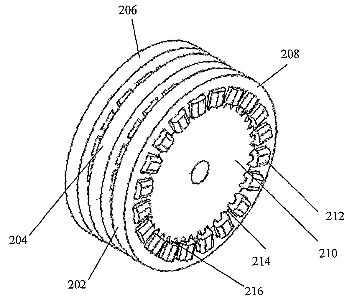
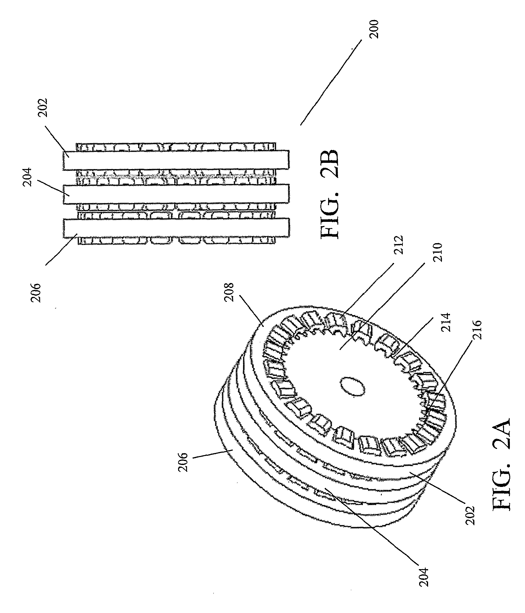
[0045]FIG. 2A illustrates a three phase S SRM (switched reluctance machine) 200 and FIG. 2B is a transverse view thereof. Each of the three phases 202, 204 and 206 are distributed along the axis of the S SRM 200, and comprise a stator 208, a rotor 210, and coils 212. The S SRM may be a motor or a generator and such would be apparent to a person having ordinary skill in the art.

[0046]The stator 208 comprises a plurality of stator poles 214 (stator poles 214 are illustrated more clearly as feature 304 in FIG. 3) extending radially inwards from an inner surface thereof. The stator poles 214 are arranged substantially equidistant along an inner circumference of the stator 208, such that a recess is formed between adjacent stator poles 214. The tips of the stator poles 214 are substantially circular and concave.

[0047]The rotor 210 is positioned inside the cylindrical c...


PUM


Abstract

The present invention provides an S SRM (switched reluctance machine), which supports one or more phases and each phase comprises a stator, a rotor and coils. The stator is hollow, cylindrical and comprises stator poles extending inwards, such that a recess is formed between adjacent stator poles. The coils are wound on the stator poles and occupy the recess. The rotor is positioned inside the stator and has poles extending outwards. The rotor and stator poles subtend an angle having a maximum value of 0.5 electrical pole pitches at a center of rotation. The different phases are distributed along the axis of the S SRM. The rotor is rotated by a reluctance torque generated by energizing a phase in a current controlled manner until the rotor rotates through a minimum commutation angle required to maintain motion; de-energizing the phase by freewheeling it by using the energy stored in it and simultaneously energizing a second sequentially adjacent phase.

Description

FIELD OF INVENTION[0001]The present invention relates to a switched reluctance machine that can be operated either as a motor or a generator. More particularly, the present invention relates to a switched reluctance machine, which supports a higher angle of commutation than the minimum required angle, and generates positive torque by freewheeling a phase during the motion of the machine through the angle which is in excess of the minimum required commutation angle.BACKGROUND OF THE INVENTION[0002]A Switched Reluctance (SR) motor is a rotating electrical machine where both the stator and the rotor have salient poles. The stator winding comprises a set of coils, each of which is wound on one stator pole. SR motors have a certain number of suitable combinations of stator and rotor poles.[0003]FIG. 1 illustrates a conventional SR motor 100. The SR motor 100 has six stator poles S1 to S6 and four rotor poles R1 to R4. θS indicates the angle subtended by a stator pole at a center of rotat...

Claims


Application Information

Patent Timeline
IPC IPC(8): H02P25/08
CPCH02K1/246H02P25/085H02K19/103H02K16/00H02P25/092
Inventor KUDLIGI, SRINIVAS
Owner KUDLIGI SRINIVAS
Why Eureka
Try Eureka