Optical fiber probe tips and methods for fabricating same

a technology of optical fiber and tips, applied in the field of optical probes, can solve the problems of limited the utility of nsom in experiments such as near-field raman spectroscopy, single molecule fluorescence, and often show scalping and other defects, and achieves high throughput, good polarization maintenance, and unique optical transmission properties.

Inactive Publication Date: 2009-01-22
UNIV OF MARYLAND
View PDF8 Cites 7 Cited by
  • Summary
  • Abstract
  • Description
  • Claims
  • Application Information

AI Technical Summary

Benefits of technology

[0015]An exemplary embodiment of the present disclosure includes the use of elliptical core single-mode fiber such as E Core™ PM fiber available from KVH Industries, Inc. of Middletown, R.I., USA. Probes developed from this fiber in accordance with methods described herein have unique optical transmission properties such as polarization dependent throughput, good polarization maintenance, and very high throughput.
[0016]An exemplary method disclosed herein also includes heating the fiber prior to etching to diffuse doping non-uniformities. Such an artifact is present in the E Core™ PM fiber as a thin low doped filament of silica within the core and running parallel to the fiber axis. This filament has a lower germanium doping than the surrounding region of the core and therefore etches faster. This results in a crater being formed on the end of the core tip after etching. Heating the fiber prior to etching diffuses this filament and eliminates the formation of the crater.

Problems solved by technology

This approach suffers from very high attenuation of the optical power traveling within the tip, which limits the utility of NSOM in experiments such as near-field Raman Spectroscopy, single molecule fluorescence, etc.
The surfaces of these tips produced by this method frequently show scalping and other defects caused of the unstable balance between gravity, surface tension and van der Waals forces involved in chemical wetting of the fiber surface.
Further, the apex of the resulting tips may not be well centered within the core again because of this instability.
The remaining cladding forms a comparatively large shoulder which interferes with light propagation in reflective NSOM configurations.
The obvious disadvantages of a multi-step process are additional processing costs and the increased opportunity for damage to the tips in process.
In a conventional circular core optical fiber, it is very difficult to control the polarization, which changes in response to stress and temperature induced geometrical non-uniformities in the core-clad geometry. T. Mitsui and T. Sekiguchi describe tips produced from stress-induced birefringent fibers mechanical pulling in their publication, “Observation of polarization property in near-field optical imaging by a polarization-maintaining fiber probe,” Journal of Electron Microscopy, vol.
The resulting tips have very low throughput, which limits the utility of NSOM in experiments such as Near-field Raman Spectroscopy, single molecule fluorescence, etc.

Method used


Image

  • Optical fiber probe tips and methods for fabricating same
  • Optical fiber probe tips and methods for fabricating same
  • Optical fiber probe tips and methods for fabricating same

Examples


Embodiment Construction

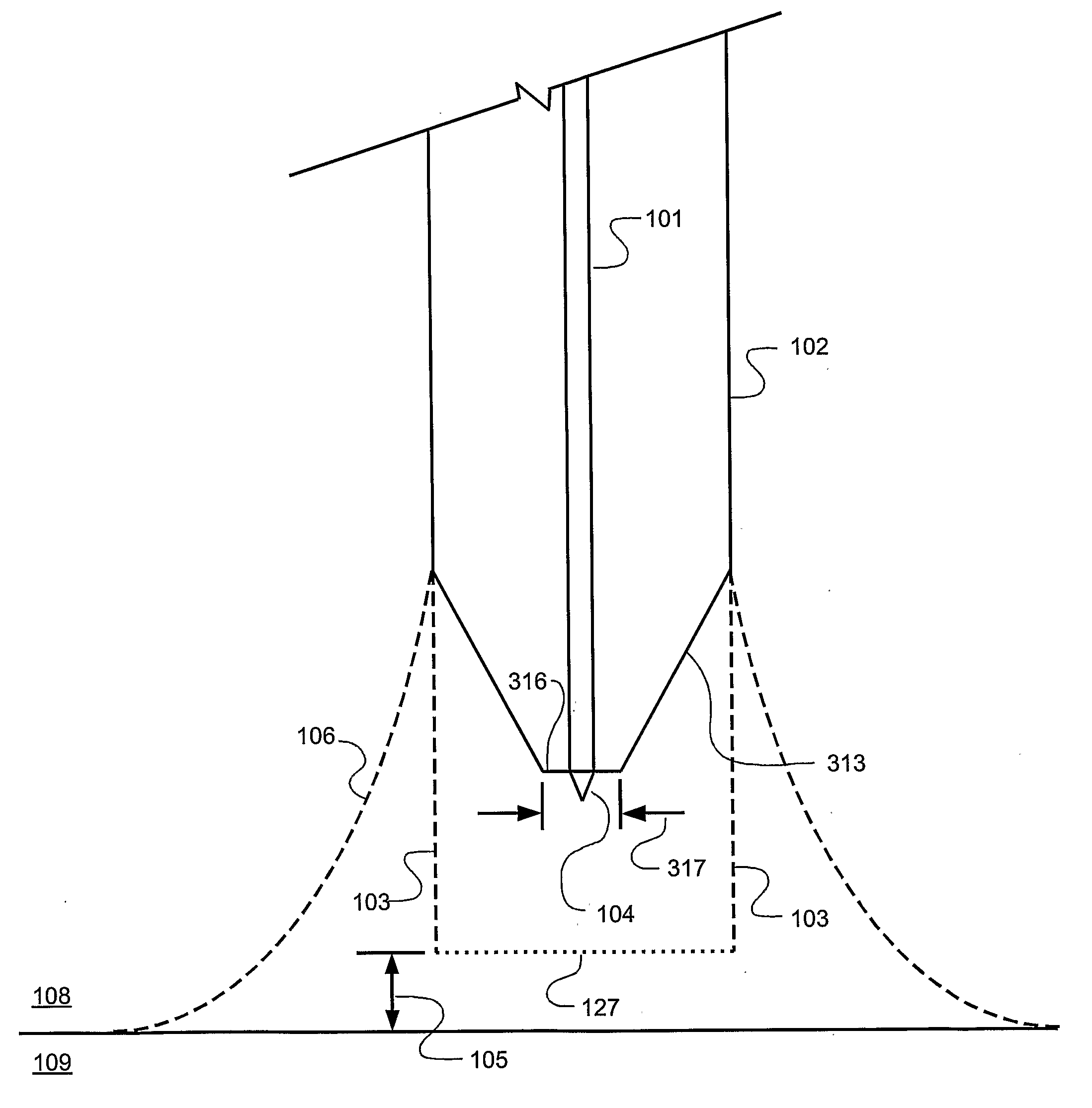
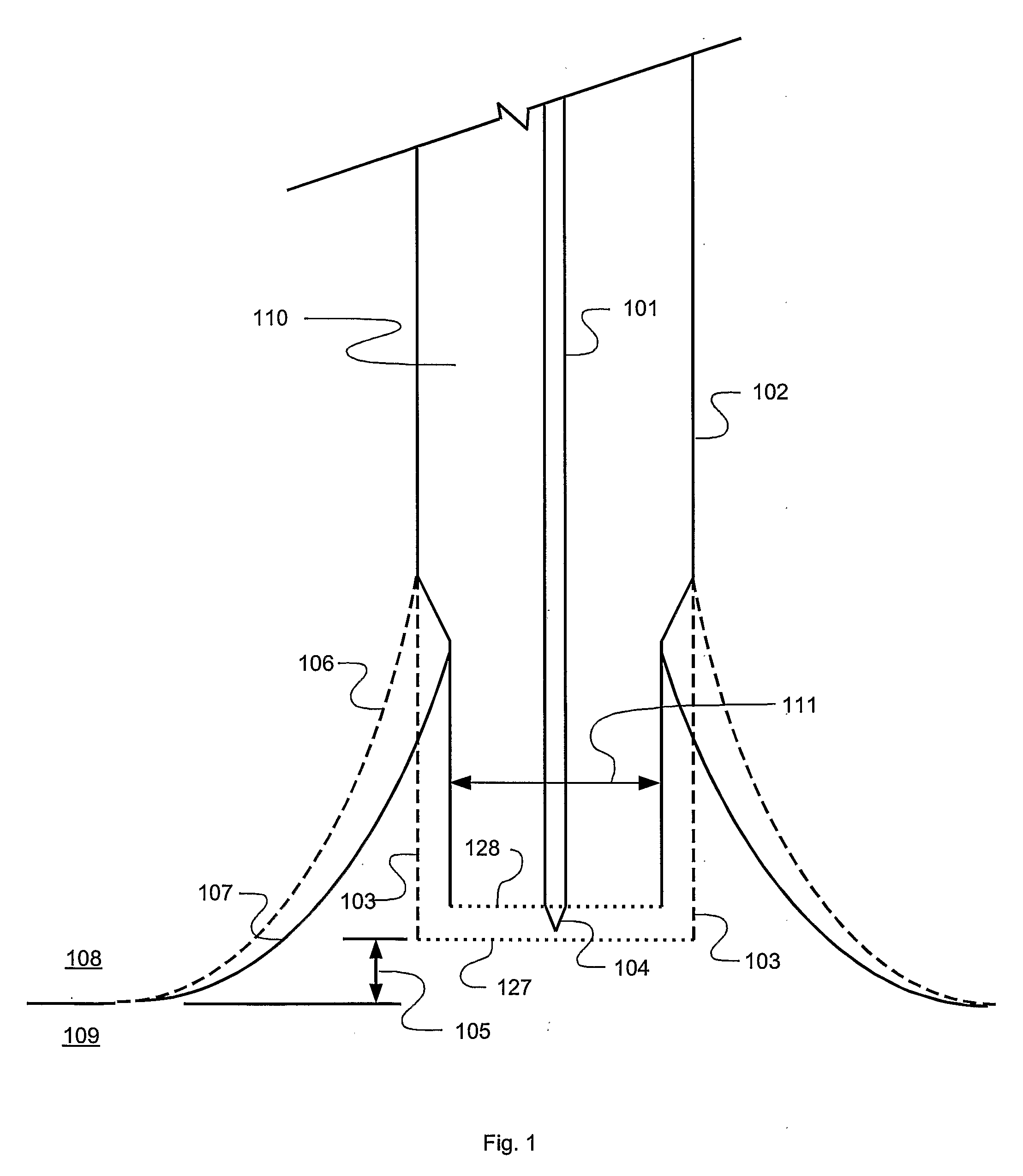
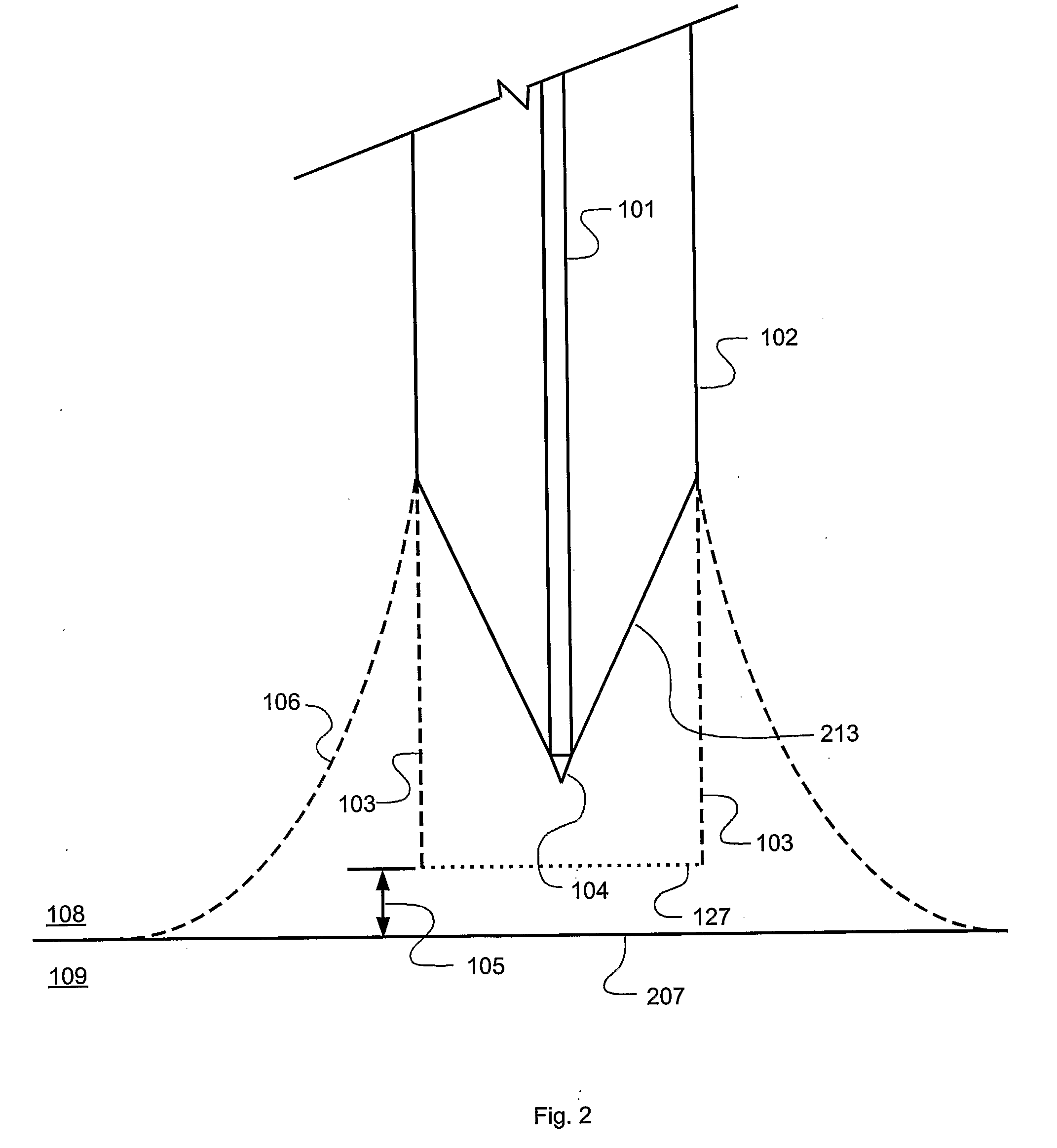
[0030]A process in accordance with an exemplary embodiment of the present disclosure is shown in FIG. 1 in which the distal end of an optical fiber, designated 110, which may be, for example, part number SM600 available from Thorlabs, Inc. of Newton, N.J., USA, is immersed a particular height 105 in an etching solution 109. The etching solution can be, for example, 30:1 buffered oxide etch (BOE) available from Mallinckrodt Baker, Inc. of Phillipsburg, N.J., USA. The optical fiber 110 consists of a glass core 101 and cladding 102. If the fiber 110 is supplied with a plastic jacket or other covering which could interfere with the etching process, the plastic jacket is removed from the region to be etched. The material generally designated 108 and located above the etching solution may be air. In one embodiment, material 108 is an inert layer of, for example, isooctane, which prevents evaporation of the etching solution and protects the upper portion of the fiber 110 from damage from B...


PUM


Abstract

Optical fiber probe tips and methods for fabricating the same are presented. One method entails immersing a distal end of an optical fiber having a cladding and a core into an etching solution and simultaneously etching the cladding and the core using the etching solution for tapering the cladding and the core to form a tapered cladding and a tapered core tip. The optical fiber probe tips are suitable for near-field, scanning, optical microscopy (NSOM).

Description

PRIORITY[0001]This application claims the benefit of U.S. Provisional Application No. 60 / 675,314 filed on Apr. 27, 2005; the entire contents of which are incorporated herein by reference.STATEMENT REGARDING FEDERALLY SPONSORED RESEARCH OR DEVELOPMENT[0002]This invention was made with government support under Contract Number MDA90403C0464 awarded by the National Security Agency. The government has certain rights in the invention.BACKGROUND[0003]1. Technical Field[0004]The present disclosure relates to the field of optical probes for use in near-field scanning optical microscopy (NSOM), also commonly referred to as scanning near-field optical microscopy (SNOM).[0005]2. Description of the Prior Art[0006]Near-field optical microscopy (NSOM) forms an image of a specimen by scanning an aperture over specimen or object. Utilizing a sub-wavelength aperture, which is an aperture smaller than the wavelength of light used to form the image, allows spatial resolution surpassing the diffraction ...

Claims


Application Information

Patent Timeline
Patent Type & Authority Applications(United States)
IPC IPC(8): G02B6/25B44C1/22G01Q10/00G01Q60/18G01Q60/22G01Q70/16
CPCB82Y20/00G01Q60/22B82Y35/00
Inventor SCHMADEL, DONALD C.DREW, HOWARD DENNISADIGA, VIVEKANANDACUBILLOS-MORAGA, ANTON MAX
Owner UNIV OF MARYLAND
Why Eureka
Try Eureka