System for determining spinal implants

a technology for spinal implants and spinal cords, applied in the field of spinal abnormalities treatment systems, can solve the problems of large variation in patient outcomes, pain alone cannot be detected by x-ray or scan,

Inactive Publication Date: 2009-01-22
NEUBARDT SETH L
View PDF10 Cites 39 Cited by
  • Summary
  • Abstract
  • Description
  • Claims
  • Application Information

AI Technical Summary

Problems solved by technology

Because any given surgeon's intuition is usually based on his or her training and the fellowship program they completed, the current practice of evaluating patients' spines and identifying implant devices to treat suspected abnormalities is fraught with uncertainties, and it results in patient outcomes that vary widely.
And pain alone can not be detected by way of an x-ray or scan.

Method used


Image

  • System for determining spinal implants
  • System for determining spinal implants
  • System for determining spinal implants

Examples


example one

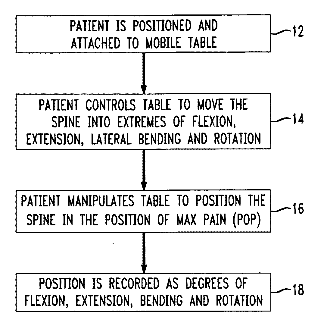
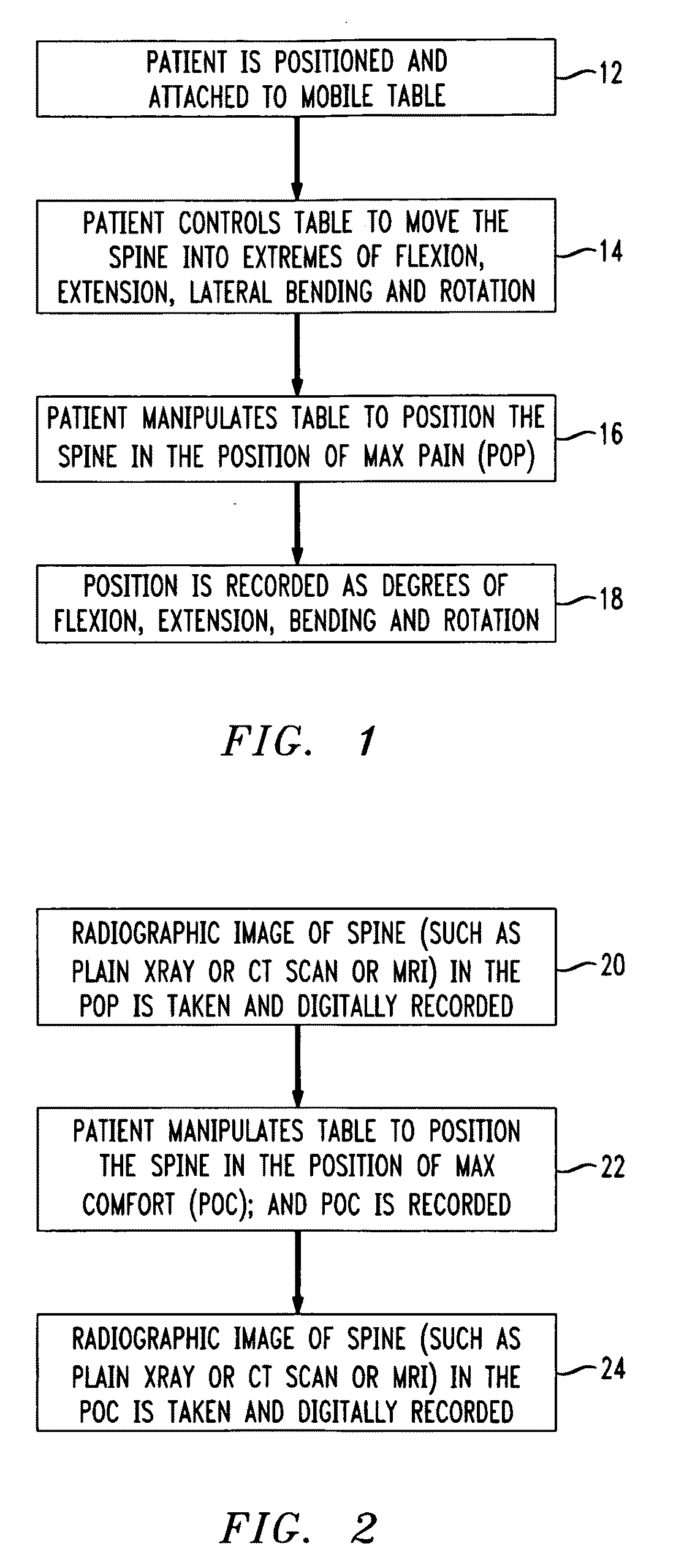
[0029]Patient 1 is positioned and attached to a mobile surgical table 102 such as, e.g., the SpineSix table mentioned above. The patient controls the table 102 to move his / her spine into extremes of flexion, extension, bending, rotation, distraction and compression. The patient then manipulates the table to position their spine in a position where he or she experiences maximum pain (POP). The table position is recorded in terms of degrees of flexion, extension, bending, rotation, distraction and compression.

[0030]FIG. 8 is a radiographic image (plain x-ray) of the patient's spine in the POP, obtained from a scanner 104 in FIG. 7. The image, which may be taken and recorded digitally, is a plain lateral x-ray in which selected angles of lordosis and kyphosis associated with the motion segment are measured. In this example, MRI images are preferred instead of plain x-rays so that anatomical characteristics of the patient's POP and POC can be quantified once the positions are determined...

example two

[0035]Patient 2 is positioned and attached to the mobile table 102. The patient controls the table 102 to move his / her spine into extremes of flexion, extension, bending, rotation, distraction and compression. The patient then manipulates the table to position their spine in a position where he or she experiences maximum pain (POP). The table position is recorded in terms of degrees of flexion, extension, bending, rotation, distraction and compression.

[0036]MRI radiographic lateral images of the patient's spine in the POP are taken by the scanner 104 and digitally recorded. FIG. 13 shows the sagittal (lateral) view of the MRI taken with patient 2 in the POP. The image of reveals anterior shift of L4 on L5 which is consistent with instability at that level and therefore presumed to be a spinal level of pain. Further, the image shows a posterior shift of L5 on S1 which is consistent with instability at that level and is therefore also presumed to be a spinal level of pain. Accordingly...


PUM


Abstract

A system for determining spinal implants includes a surgical table that moves a patient secured on the table into different positions in response to patient command, including a position of pain (POP) where the patient experiences the most pain from one or more affected levels of the spine, and a position of comfort (POC) where the patient has the least amount of pain. A scanner scans the patient on the table at least at the POP and the POC, and produces corresponding radiographic image data. Image processing apparatus coupled to the scanner quantifies changes in the relative position of adjacent vertebra at each affected level when the vertebra move from their configuration in the patient's POP, to their configuration in the patient's POC. The apparatus can then select an optimal implant device from among a number of devices whose characteristics are stored in a system database.

Description

CROSS REFERENCE TO RELATED APPLICATION[0001]This application claims priority under 35 U.S.C. § 119(e) of U.S. Provisional Patent Application No. 60 / 937,055 filed Jun. 25, 2007, and entitled “System for Treatment of Spinal Abnormalities Using Patient Selected Positions”.BACKGROUND OF THE INVENTION[0002]1. Field of the Invention[0003]The present invention concerns systems for treating spinal abnormalities by the use of implant devices.[0004]2. Discussion of the Known Art[0005]Surgeons and clinical practitioners use radiographic tools such as MRI scans and X-rays, together with their experience and intuition to evaluate if a patient's spine is configured within a so-called “normal” range. If not, the surgeon then decides how much restoration or positional variance must be imparted to the spine to eliminate or reduce back pain using procedures such as, e.g., spinal fusion or disc replacement. Because any given surgeon's intuition is usually based on his or her training and the fellowshi...

Claims


Application Information

Patent Timeline
Patent Type & Authority Applications(United States)
IPC IPC(8): A61F5/00
CPCA61B5/055A61B5/1077A61B5/4504A61B5/4561A61B6/505A61F2/44A61B2019/502A61B2019/505A61B2019/5236A61B2019/5238A61B19/50A61B34/10A61B2034/102A61B2034/105A61B2090/374A61B2090/376
Inventor NEUBARDT, SETH L.
Owner NEUBARDT SETH L
Why Eureka
Try Eureka