Acceleration sensor

a sensor and acceleration technology, applied in the field of acceleration sensors, can solve the problems of excessive displacement of resistive elements, affecting and flexing of beam portions, so as to avoid breakage of stopper portions, prevent stress generated, and improve the endurance of acceleration sensors

a sensor and acceleration technology, applied in the field of acceleration sensors, can solve the problems of excessive displacement of resistive elements, affecting and flexing of beam portions, so as to avoid breakage of stopper portions, prevent stress generated, and improve the endurance of acceleration sensors

US20090025478A1Inactive Publication Date: 2009-01-29LAPIS SEMICON CO LTD

Image

  • Acceleration sensor
  • Acceleration sensor
  • Acceleration sensor

Examples


first embodiment

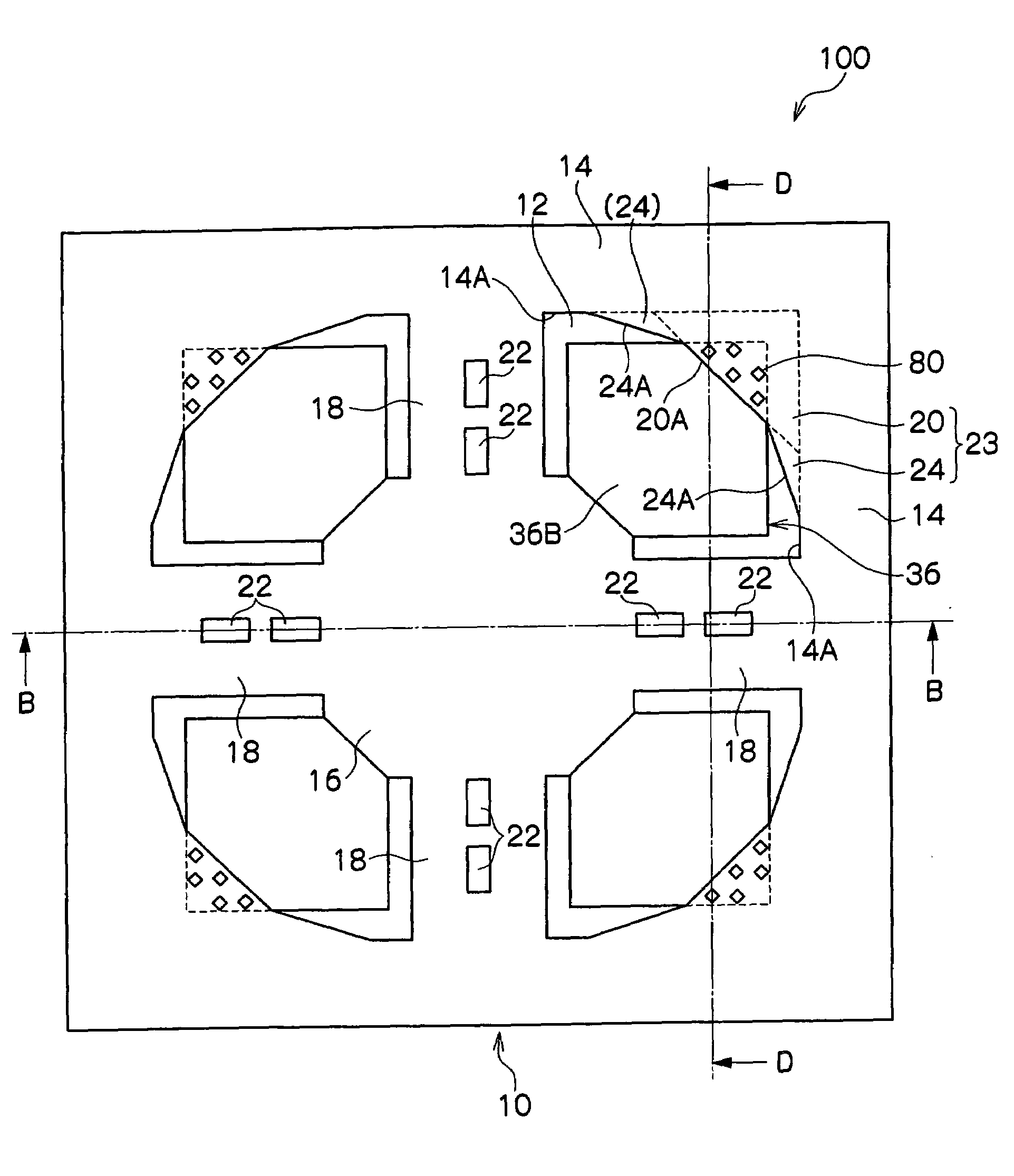
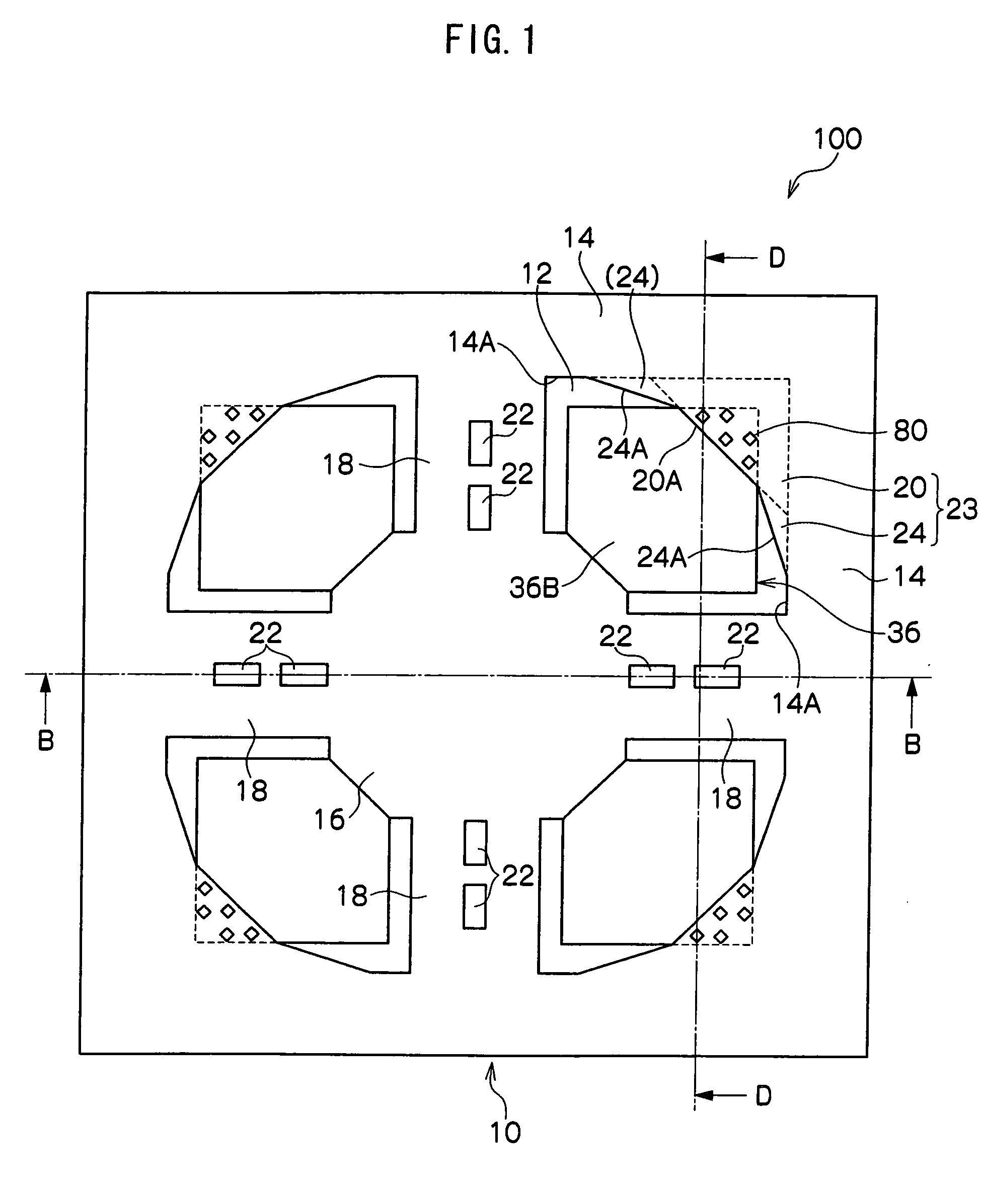
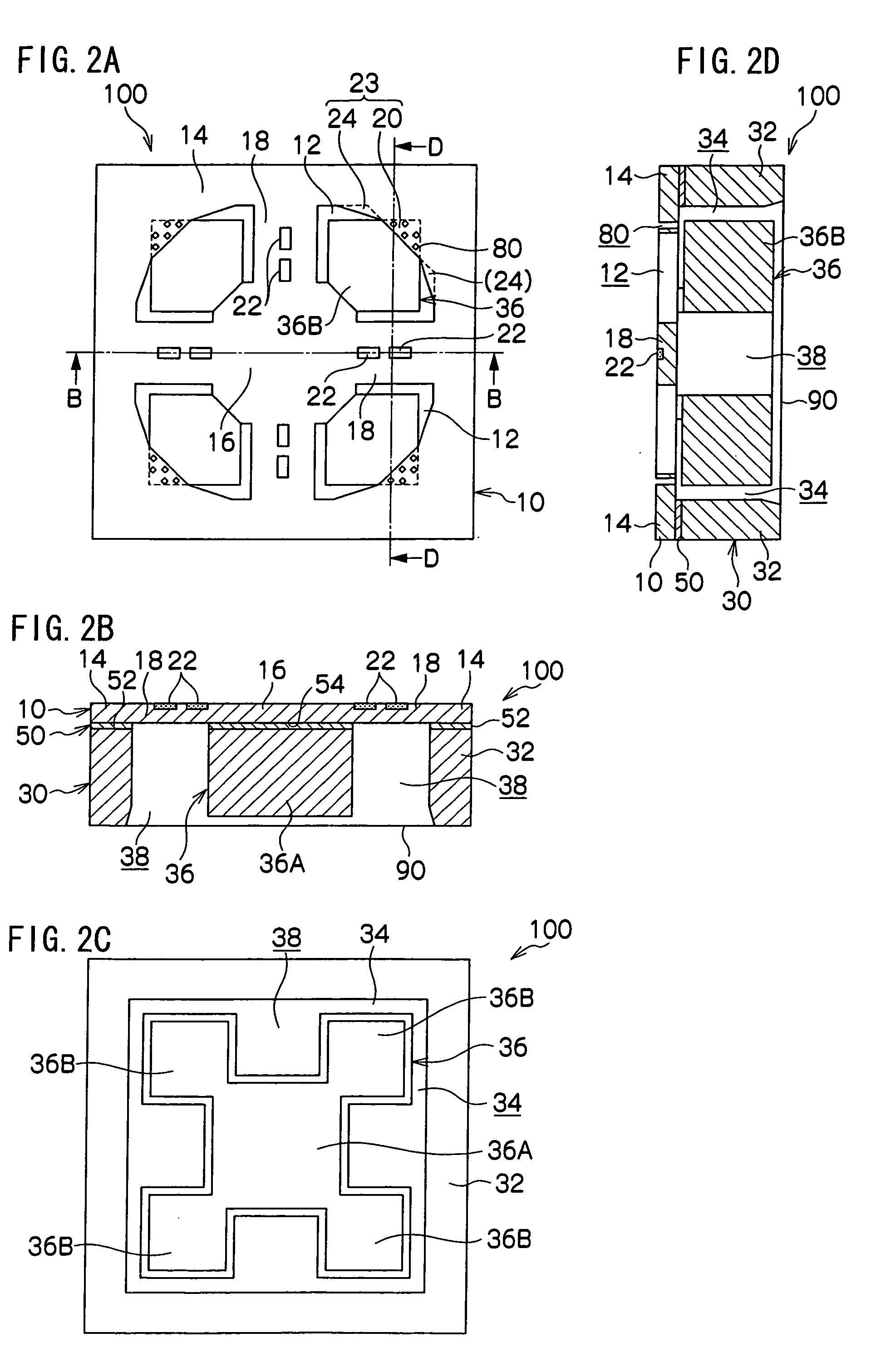
[0038]An acceleration sensor 100 relating to a first exemplary embodiment of the present invention will be described with reference to FIG. 1 to FIG. 10.

[0039]The acceleration sensor 100, as shown in FIG. 2B, is formed by etching and the like to an SOI (silicon on insulator) wafer, in which a first silicon substrate 10 with thickness about 5 μm and a second silicon substrate 30 with thickness about 525 μm are stuck together with an insulator layer 50 therebetween.

[0040]As shown in FIG. 1 and FIG. 2A, a single one of the silicon substrate 10 of the acceleration sensor 100 has a substantially square shape with sides of about 2.5 mm. Peripheral edge portions of the silicon substrate 10 are supported by pedestal portions 32, which will be described later (see FIG. 2B). Four opening portions 12 are provided at an inner side of the silicon substrate 10. Thus, respective regions of a peripheral fixing portion 14, a weight fixing portion 16, beam portions 18 and stoppers 23 are formed.

[0041...

second embodiment

[0081]Next, a second exemplary embodiment of the acceleration sensor 100 of the present invention will be described in accordance with FIG. 11.

[0082]Here, members the same as in the first exemplary embodiment are assigned the same reference numerals and will not be described.

[0083]As shown in FIG. 11, differently from the first exemplary embodiment, opening edges 26A of reinforcement portions 26, which face the opening portions 12, have curved forms, and are provided so as to join with opening edges 20A of the stopper portions 20 and opening edges 14A of the peripheral fixing portion 14.

[0084]Consequently, localized changes of shape will not occur at the opening edges 14A, the opening edges 20A and the opening edges 26A. Therefore, localized concentrations of stresses caused by the peripheral weight portions 36B abutting the stopper portions 20 can be prevented.


PUM


Abstract

The present invention provides an acceleration sensor that improves endurance by avoiding damage to stopper portions. When a downward vibration is applied to a weight member and the weight member displaces downward, a bottom face of the weight member abuts a bottom plate, and the weight member stops and downward displacement is obstructed. Furthermore, when the weight member displaces upward, peripheral weight portions abut stopper portions, and the weight member stops and upward displacement is obstructed. Because displacement of the weight member is obstructed by abutting the stopper portions, if the strength of the stopper portions is low, the stopper portions may be damaged. However, by providing reinforcement portions which reinforce the stopper portions, damage to the stopper portions may be prevented, and endurance of the acceleration sensor is improved.

Description

CROSS-REFERENCE TO RELATED APPLICATION[0001]This application claims priority under 35 USC 119 from Japanese Patent Application No. 2007-182966, the disclosure of which is incorporated by reference herein.BACKGROUND OF THE INVENTION[0002]1. Field of the Invention[0003]The present invention relates to an acceleration sensor for sensing acceleration in three axial directions X, Y and Z.[0004]2. Description of the Related Art[0005]According to an acceleration sensor described in Japanese Patent Application Laid-Open (JP-A) No. 2004-198243, when a vibration is propagated from an object of acceleration measurement and a weight member mounted at a weight fixing portion vibrates, the weight fixing portion displaces. As a result, beam portions adjoining the weight fixing portion flex, and resistance values of resistive elements attached to the beam portions change with the flexing of the beam portions. On the basis of this change in the resistance values, an acceleration of the acceleration ...

Claims


Application Information

Patent Timeline
29 Jan 2009
Publication
US20090025478A1
IPC
G01P15/12; H01L29/84
CPC
B81B3/0072; B81B2201/0235; G01P15/18; G01P15/123; G01P15/0802; B81B3/0051; G01P2015/0842
Inventors
MIKI, SHINSUKE