Modular coiled tubing and sectional pipe drilling rig

a drilling rig and module technology, applied in drilling machines and methods, surveying, core removal, etc., can solve the problems of complicated moving, limited drilling process, and need to transport extremely heavy equipment to and from the drilling site, and achieve convenient movement, reasonable weight, and easy assembly and disassembly on site

Inactive Publication Date: 2009-01-29
FOREMOST INDS
View PDF4 Cites 26 Cited by
  • Summary
  • Abstract
  • Description
  • Claims
  • Application Information

AI Technical Summary

Benefits of technology

[0004]It is an object of the present invention to provide an overall drill rig formed of readily separable units or modules each of which is of a weight and dimension which can be more conveniently moved from site to site each with more reasonable weight and within set requirements, and yet also be readily assembled and disassembled on site.

Problems solved by technology

In any event, the coiled tubing process has limitations under certain drilling conditions, and as a result various equipment and techniques have developed to enable the switching back and forth between the two different processes in the drilling and servicing of a single well.
Various techniques have developed for combining into a single well operation the necessary components to allow quick and effective changes between the two processes, and this together with the increased tubular size has resulted in the need to transport extremely heavy equipment to and from the drilling site.
Not only does the weight and size result in complicated moving from one drill site to another in the oil field, but the weight regulations on public roadways set strict restrictions in size and weight as to what can be taken to or removed from the oil field.

Method used


Image

  • Modular coiled tubing and sectional pipe drilling rig
  • Modular coiled tubing and sectional pipe drilling rig
  • Modular coiled tubing and sectional pipe drilling rig

Examples


Embodiment Construction

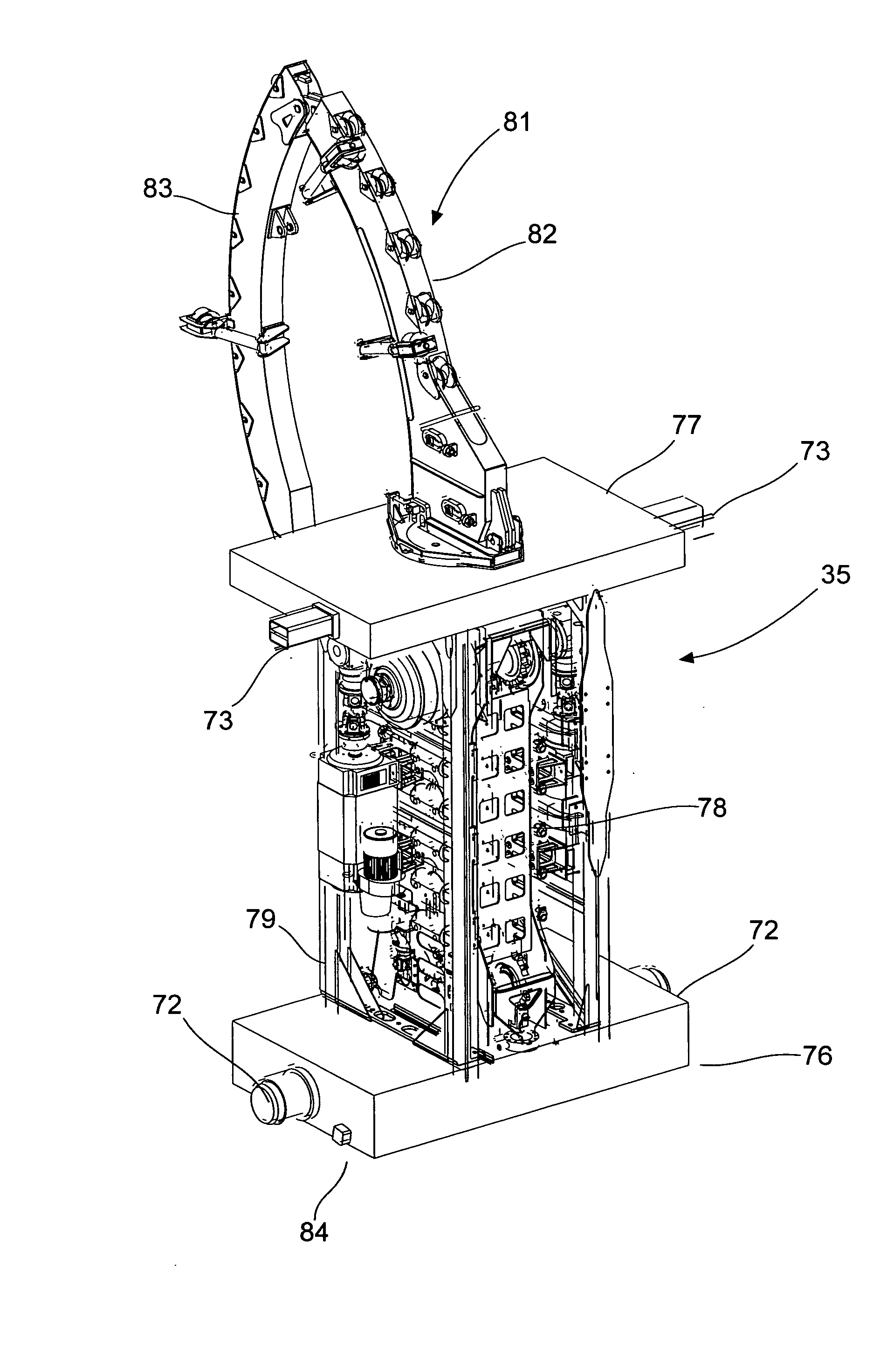
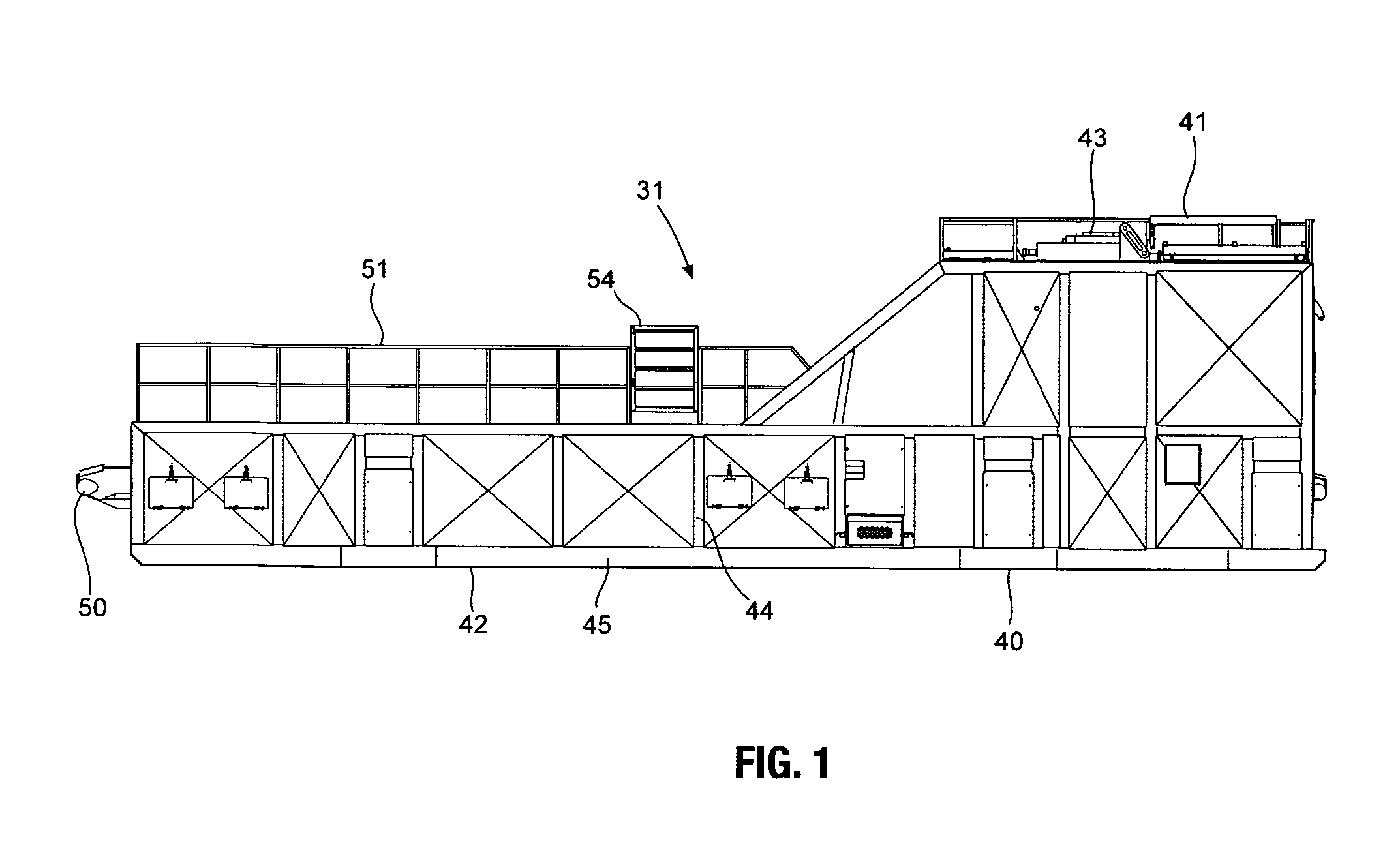
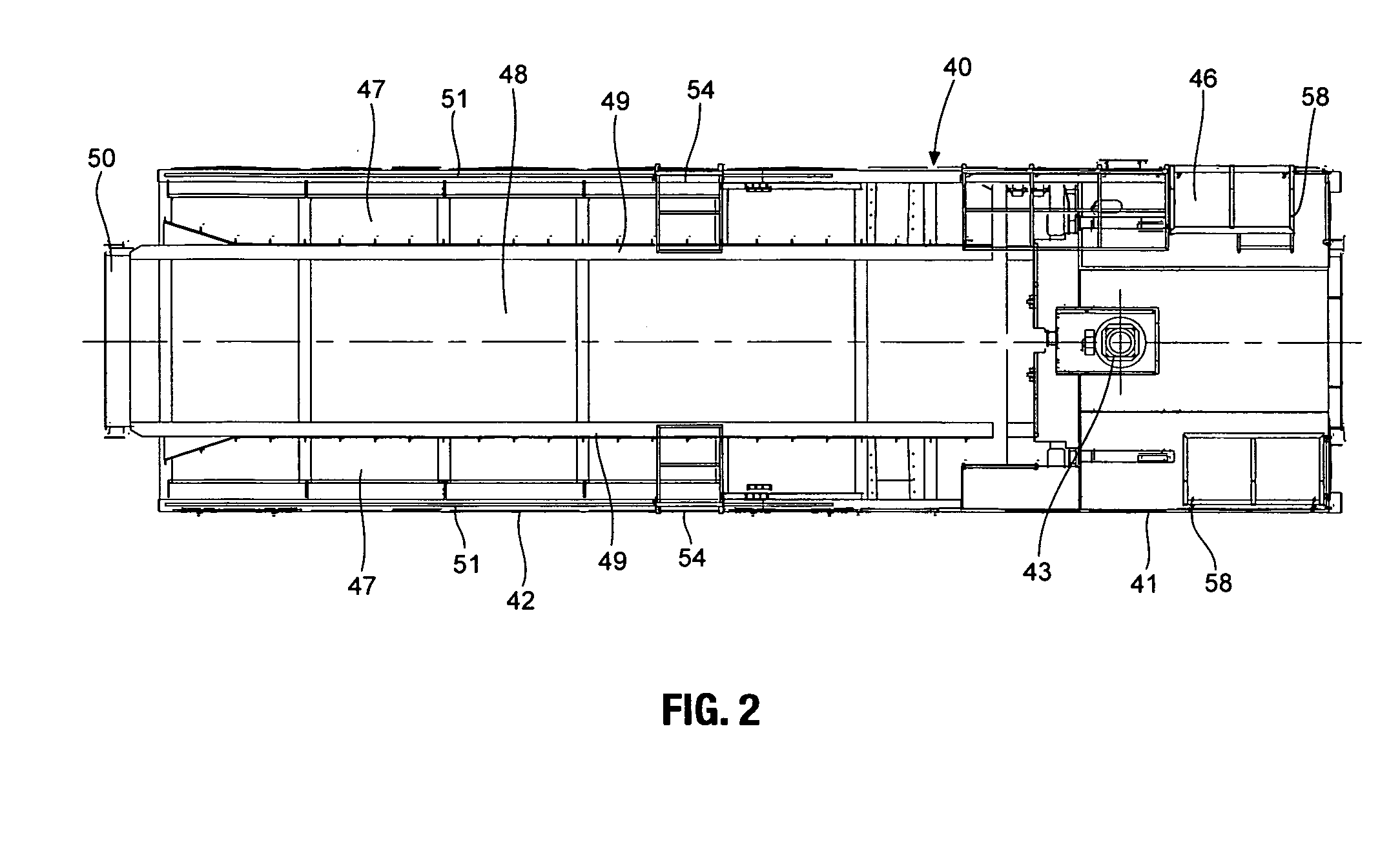
[0033]Referring first briefly to FIG. 22, there is shown a complete set up at a drilling site of rig 30 of the present invention in an operating mode and incorporating the present invention. The rig 30 includes an overall substructure or base component 31 on which there is mounted a separate drawwork / mast module, hereinafter referred to as a mast component 52. On the mast component 52 there is mounted an injector carrier 32. The mast component 52 includes an upright mast 33 which is provided with a top drive apparatus 34, the mast component being adapted to support an injector component 35 during a coiled tubing operation. Another separate module or transport component 36 carries a reel 37 which furthers supplies coiled tubing 38 during a drilling operation, or receives the coiled tubing during its withdrawal from a well.

[0034]In an operatively assembled form in FIG. 1, there is shown the first module or base component 31 which is in the form of a completely separable substructure 4...


PUM


Abstract

A drilling rig for use in both coiled tubing injection and rigid threaded pipe operations, and consisting of a number of separably transportable modules which are assembled on site for carrying out the operations. Included in the modules are a substructure component, a mast component and an injector component. In setting up for operation, the mast component is combined on site with the substructure component which supports the assembled rig over the borehole. The mast component in location provides a loading area to support the injector component in a position for ready loading of an injector included in the injector component into the mast when required for a coiled tubing operation.

Description

CROSS REFERENCE TO RELATED APPLICATION[0001]This application claims the benefit of convention priority on Canadian Patent Application No. 2,595,666, filed Jul. 25, 2007, entitled Modular Coiled Tubing and Sectional Pipe Drilling Rig.FIELD OF THE INVENTION[0002]This invention relates to a drilling rig of the type used in drilling and servicing boreholes, and more particularly, to one formed of separate units or modules, capable of being readily transported and then assembled for use with coiled tubing or threaded pipe sections.BACKGROUND OF THE INVENTION[0003]The use of the coiled tubing technique in forming and servicing well boreholes has gained wide spread acceptance in the last decade due to the convenience and speed of using a continuous length of tubing from a reel as opposed to the amount of labour and time required in using the conventional method of joining and disassembling of sections of lengths of threaded pipe. Initially, it was a common practice to mount a reel of the c...

Claims


Application Information

Patent Timeline
Patent Type & Authority Applications(United States)
IPC IPC(8): E21B19/08
CPCE21B19/22E21B15/003
Inventor CALLANDER, GARY R.PLESKIE, ALLAN J.NIEMCZEWSKI, VOYTEK
Owner FOREMOST INDS
Why Eureka
Try Eureka